Enterprise Capacity 2.5 HDD SAS Product Manual Standard Models Self-Encrypting Drive Models SED FIPS140-2 Models 4096 Native ST2000NX0263 ST1000NX0323 ST2000NX0323 ST1000NX0363 ST2000NX0333 512 Emulation ST2000NX0273 ST1000NX0333 ST2000NX0343 ST1000NX0373 ST2000NX0353 512 Native ST2000NX0433 ST1000NX0453 100751316, Rev.
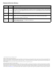
Document Revision History Revision Date Description of Change Rev. A 07/31/2014 Initial release. Rev. B Pages - fc, bc, 8, 17, 23-24 & 43: Applied new logo, applied new page numbering convention, deleted Index [no longer needed], removed “Canadian Department of Communications”, changed MTBF to 2M, changed to "Maximum 01/29/2015 Rated Workload" & updated Workload text, delete text in Section 5.2.1, updated DC power tables & added Sanitize (Overwrite) command. Rev.
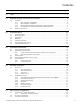
Contents Seagate® Technology Support Services . . . . . . . . . . . . . . . . . . . . . . . . . . . . . . . . . . . . . . . . . . . . . . . . . . . . . . . . 6 1.0 Scope . . . . . . . . . . . . . . . . . . . . . . . . . . . . . . . . . . . . . . . . . . . . . . . . . . . . . . . . . . . . . . . . . . . . . . . . . . . . . . . . . . . . . . . 7 2.0 Applicable standards and reference documentation. . . . . . . . . . . . . . . . . . . . . . . . . . . . . . . . . . . . . . . . . . . . 8 2.1 Standards . . . .
Contents 6.4 6.5 6.6 6.3.1 Conducted noise immunity . . . . . . . . . . . . . . . . . . . . . . . . . . . . . . . . . . . . . . . . . . . . . . . . . . . . . . . .25 6.3.2 Power sequencing . . . . . . . . . . . . . . . . . . . . . . . . . . . . . . . . . . . . . . . . . . . . . . . . . . . . . . . . . . . . . . . . .25 6.3.3 Current profiles . . . . . . . . . . . . . . . . . . . . . . . . . . . . . . . . . . . . . . . . . . . . . . . . . . . . . . . . . . . . . . . . . . . .25 Power dissipation . . . . .
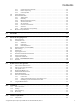
Contents 11.2 11.3 11.4 11.5 11.6 11.7 11.1.1 Task management functions . . . . . . . . . . . . . . . . . . . . . . . . . . . . . . . . . . . . . . . . . . . . . . . . . . . . . . .40 11.1.2 Task management responses . . . . . . . . . . . . . . . . . . . . . . . . . . . . . . . . . . . . . . . . . . . . . . . . . . . . . .40 Dual port support . . . . . . . . . . . . . . . . . . . . . . . . . . . . . . . . . . . . . . . . . . . . . . . . . . . . . . . . . . . . . . . . . . . . . . . . . . . .
Figures Figure 1. Figure 2. Figure 3. Figure 4. Figure 5. Figure 6. Figure 7. Figure 8. Figure 9. Figure 10. Figure 11. Figure 12. Figure 13. Current profiles for 2TB models . . . . . . . . . . . . . . . . . . . . . . . . . . . . . . . . . . . . . . . . . . . . . . . . . . . . . . . . . . . . . . . . . 25 Current profiles for 1TB models . . . . . . . . . . . . . . . . . . . . . . . . . . . . . . . . . . . . . . . . . . . . . . . . . . . . . . . . . . . . . . . . . .
Seagate® Technology Support Services For information regarding online support and services, visit: http://www.seagate.com/contacts/ For information regarding Warranty Support, visit: http://www.seagate.com/support/warranty-and-replacements/ For information regarding data recovery services, visit: http://www.seagate.com/services-software/seagate-recoveryservices/recover/ For Seagate OEM, Distribution partner and reseller portals, visit: http://www.seagate.com/partners Seagate Enterprise Capacity 2.
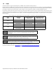
1.0 Scope This manual describes Seagate® Enterprise Capacity 2.5 HDD v3 SAS (Serial Attached SCSI) disk drives. Enterprise Capacity 2.5 HDD v3 drives support the SAS Protocol specifications to the extent described in this manual. The SAS Interface Manual (part number 100293071) describes the general SAS characteristics of this and other Seagate SAS drives.
2.0 Applicable standards and reference documentation The drives documented in this manual have been developed as system peripherals to the highest standards of design and construction. The drives depend on host equipment to provide adequate power and environment for optimum performance and compliance with applicable industry and governmental regulations. Special attention must be given in the areas of safety, power distribution, shielding, audible noise control, and temperature regulation.
A number of parts and materials in Seagate products are procured from external suppliers. We rely on the representations of our suppliers regarding the presence of RoHS substances in these parts and materials. Our supplier contracts require compliance with our chemical substance restrictions, and our suppliers document their compliance with our requirements by providing material content declarations for all parts and materials for the disk drives documented in this publication.
3.0 General description Enterprise Capacity 2.5 HDD v3 SAS drives provide high performance, high capacity data storage for a variety of systems including engineering workstations, network servers, mainframes, and supercomputers. The Serial Attached SCSI interface is designed to meet next-generation computing demands for performance, scalability, flexibility and high-density storage requirements. Enterprise Capacity 2.
• • Vertical, horizontal, or top down mounting Zone bit recording (ZBR) Self-Encrypting Drive models have the following additional features: • 16 independent data bands • Authenticated firmware download • Automatic data encryption/decryption • Controlled access • Cryptographic erase of user data for a drive that will be repurposed or scrapped • Drive locking • Random number generator 3.
3.5 Formatted capacities Standard OEM models are formatted to 512 bytes per block for 512E (emulation) and 512N (native) drives and 4096 bytes per block for 4096N (native) drives. The block size is selectable at format time. Supported block sizes are 512, 520, 524, and 528 for 512E and 512N drives and 4096, 4160, 4192, and 4224 for 4096N drives. Users having the necessary equipment may modify the data block size before issuing a format command and obtain different formatted capacities than those listed.
4.0 Performance characteristics This section provides detailed information concerning performance-related characteristics and features of Enterprise Capacity 2.5 HDD v3 drives. 4.
4.3 Start/stop time The drive accepts the commands listed in the SAS Interface Manual less than 3 seconds after DC power has been applied. If the drive receives a NOTIFY (ENABLE SPINUP) primitive through either port and has not received a START STOP UNIT command with the START bit equal to 0, the drive becomes ready for normal operations within 20 seconds (excluding the error recovery procedure).
4.5.1 Caching write data Note Write caching in this section is the traditional SCSI write caching (WCE=1) where writes are not protected on power loss. Note Refer to the SAS Interface Manual for more detail concerning the cache bits. Write caching is a write operation by the drive that makes use of a drive buffer storage area where the data to be written to the medium is stored while the drive performs the Write command. WCE=0 provides NVC-protected write caching over a small portion of the DRAM.
5.0 Reliability specifications The following reliability specifications assume correct host and drive operational interface, including all interface timings, power supply voltages, environmental requirements and drive mounting constraints. Seek error rate: Read Error Rates1 Recovered Data Unrecovered Data Miscorrected Data Interface error rate: Mean Time Between Failure (MTBF): Annualized Failure Rate (AFR): Preventive maintenance: 1.
5.2 Reliability and service The reliability of Enterprise Capacity 2.5 HDD v3 disk drives can be enhanced by ensuring that the drive receives adequate cooling. Section 6.0 provides temperature measurements and other information that may be used to enhance the service life of the drive. Section 10.2 provides recommended air-flow information. 5.2.1 Annualized Failure Rate (AFR) and Mean Time Between Failure (MTBF) The production disk drive shall achieve an annualized failure-rate of 0.
Note The drive’s firmware monitors specific attributes for degradation over time but can’t predict instantaneous drive failures. Each monitored attribute has been selected to monitor a specific set of failure conditions in the operating performance of the drive and the thresholds are optimized to minimize “false” and “failed” predictions. Controlling S.M.A.R.T. The operating mode of S.M.A.R.T. is controlled by the DEXCPT and PERF bits on the Informational Exceptions Control mode page (1Ch).
5.2.5 Thermal monitor Enterprise Capacity 2.5 HDD v3 drives implement a temperature warning system which: 1. Signals the host if the temperature exceeds a value which would threaten the drive. 2. Saves a S.M.A.R.T. data frame on the drive which exceeds the threatening temperature value. A temperature sensor monitors the drive temperature and issues a warning over the interface when the temperature exceeds a set threshold.
5.2.6.2 Implementation This section provides all of the information necessary to implement the DST function on this drive. 5.2.6.2.1 State of the drive prior to testing The drive must be in a ready state before issuing the Send Diagnostic command. There are multiple reasons why a drive may not be ready, some of which are valid conditions, and not errors. For example, a drive may be in process of doing a format, or another DST.
5.2.6.2.4 Log page entries When the drive begins DST, it creates a new entry in the Self-test Results Log page. The new entry is created by inserting a new self-test parameter block at the beginning of the self-test results log parameter section of the log page. Existing data will be moved to make room for the new parameter block. The drive reports 20 parameter blocks in the log page. If there are more than 20 parameter blocks, the least recent parameter block will be deleted.
6.0 Physical/electrical specifications This section provides information relating to the physical and electrical characteristics of the drive. 6.1 PowerChoiceTM power management Drives using the load/unload architecture provide programmable power management to tailor systems for performance and greater energy efficiency. The table below lists the supported PowerChoice modes. The further down in the table, the more power savings can be realized.
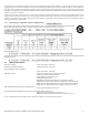
6.2 AC power requirements None. 6.3 DC power requirements The voltage and current requirements for a single drive are shown below. Values indicated apply at the drive connector. The standard drive models and the SED drive models have identical hardware, however the security and encryption portion of the drive controller ASIC is enabled and functional in the SED models. This represents a small additional drain on the 5V supply of about 10mA and a commensurate increase of about 50mW in power consumption.
Table 3 1TB standard drive DC power requirements 12.0Gb mode Notes (Amps) (Amps) (Watts) +5V +12V [2] Total [5] ±5% [2] [1] [7] 0.37 0.12 3.29 Idle_A 0.37 0.12 3.29 Idle_B 0.30 0.09 2.58 Idle_C 0.30 0.06 2.22 Standby 0.28 0.01 1.52 [3] 0.60 0.69 (peak AC) AC [3] 0.74 0.96 Delayed motor start (max) DC [1] [4] 0.31 0.03 1.91 [1] [6] 0.46 0.30 5.90 [1] 0.52 0.32 6.44 1.38 0.
6.3.1 Conducted noise immunity Noise is specified as a periodic and random distribution of frequencies covering a defined frequency range. Maximum allowed noise values given below are peak-to-peak measurements and apply at the drive power connector. +5v = 250 mV pp from 100 Hz to 20 MHz. +12v = 450 mV pp from 100 Hz to 100 KHz. 250 mV pp from 100 KHz to 20 MHz. 150 mV pp from 20 MHz to 80 MHz. 6.3.2 Power sequencing The drive does not require power sequencing.
Figure 2. Current profiles for 1TB models Note: All times and currents are typical. See Section 6.3 for maximum current requirements. Seagate Enterprise Capacity 2.5 HDD v3 SAS Product Manual, Rev.
6.4 Power dissipation 2TB models in 12Gb operation Typical power dissipation under idle conditions in 12Gb operation is 5.478 watts 18.69 BTUs per hour). To obtain operating power for typical random read operations, refer to the following I/O rate curve (see Figure 4). Locate the typical I/O rate for a drive in the system on the horizontal axis and read the corresponding +5 volt current, +12 volt current, and total watts on the vertical axis. To calculate BTUs per hour, multiply watts by 3.4123.
6.5 Environmental limits Temperature and humidity values experienced by the drive must be such that condensation does not occur on any drive part. Altitude and atmospheric pressure specifications are referenced to a standard day at 58.7°F (14.8°C). To maintain optimal performance drives should be run at nominal drive temperature and humidity. Note 6.5.1 Temperature a. Operating 41°F to 131°F (5°C to 55°C) drive temperature range with a maximum temperature gradient of 36°F (20°C) per hour.
c. Packaged Seagate finished drive bulk packs are designed and tested to meet or exceed applicable ISTA and ASTM standards. Volume finished drives will be shipped from Seagate factories on pallets to minimize freight costs and ease material handling. Seagate finished drive bulk packs may be shipped individually. For less than full shipments, instructions are printed on the bulk pack carton for minimum drive quantities and proper drive placement. Figure 5. Recommended mounting .
6.5.5 Air cleanliness The drive is designed to operate in a typical office environment with minimal environmental control. 6.5.6 Corrosive environment Seagate electronic drive components pass accelerated corrosion testing equivalent to 10 years exposure to light industrial environments containing sulfurous gases, chlorine and nitric oxide, classes G and H per ASTM B845. However, this accelerated testing cannot duplicate every potential application environment.
6.6 Mechanical specifications Refer to Figure 6 for detailed mounting configuration dimensions. See Section 10.3, “Drive mounting.” Weight: 2TB models 1TB models 198 g 190 g 0.437 lb 0.419 lb . Note Figure 6. These dimensions conform to the Small Form Factor Standard documented in SFF-8201 and SFF-8223, found at www.sffcommittee.org. Mounting configuration dimensions Seagate Enterprise Capacity 2.5 HDD v3 SAS Product Manual, Rev.
7.0 About FIPS The Federal Information Processing Standard (FIPS) Publication 140-2 is a U.S. Government Computer Security Standard used to accredit cryptographic modules. It is titled 'Security Requirements for Cryptographic Modules (FIPS PUB 140-2)' and is issued by the National Institute of Standards and Technology (NIST).
8.0 About self-encrypting drives Self-encrypting drives (SEDs) offer encryption and security services for the protection of stored data, commonly known as “protection of data at rest.” These drives are compliant with the Trusted Computing Group (TCG) Enterprise Storage Specifications as detailed in Section 2.2. The Trusted Computing Group (TCG) is an organization sponsored and operated by companies in the computer, storage and digital communications industry.
8.5 Data bands When shipped from the factory, the drive is configured with a single data band called Band 0 (also known as the Global Data Band) which comprises LBA 0 through LBA max. The host may allocate Band1 by specifying a start LBA and an LBA range. The real estate for this band is taken from the Global Band.
9.0 Defect and error management Seagate continues to use innovative technologies to manage defects and errors. These technologies are designed to increase data integrity, perform drive self-maintenance, and validate proper drive operation. SCSI defect and error management involves drive internal defect/error management and SAS system error considerations (errors in communications between the initiator and the drive).
Table 4 Read and write retry count maximum recovery times Read retry count* Maximum recovery time per LBA (cumulative, ms) Write retry count Maximum recovery time per LBA (cumulative, ms) 0 25 1 130 1 50 5 570 2 78 10 1140 3 95 15 1720 4 186 20 (default) 2520 5 (default) 295 * For read retry count, every tick ~ 5% of total error recovery. Valid range setting is 1-20. e.g.
9.6 Idle Read After Write Idle Read After Write (IRAW) utilizes idle time to verify the integrity of recently written data. During idle periods, no active system requests, the drive reads recently written data from the media and compares it to valid write command data resident in the drives data buffer. Any sectors that fail the comparison result in the invocation of a rewrite and auto-reallocation process. The process attempts to rewrite the data to the original location.
10.0 Installation Enterprise Capacity 2.5 HDD v3 disk drive installation is a plug-and-play process. There are no jumpers, switches, or terminators on the drive. SAS drives are designed to be used in a host system that provides a SAS-compatible backplane with bays designed to accommodate the drive. In such systems, the host system typically provides a carrier or tray onto which the drive needs to be mounted. Mount the drive to the carrier or tray provided by the host system using four M3 x 0.
If forced air is determined to be necessary, possible air-flow patterns are shown in Figure 9. The air-flow patterns are created by one or more fans, either forcing or drawing air as shown in the illustrations. Conduction, convection, or other forced air-flow patterns are acceptable as long as the temperature measurement guidelines of Section 6.5.1 are met. Figure 9. Air flow . Note 10.3 Image is for reference only, may not represent actual drive.
11.0 Interface requirements This section partially describes the interface requirements as implemented on Enterprise Capacity 2.5 HDD v3 drives. Additional information is provided in the SAS Interface Manual (part number 100293071). 11.1 SAS features This section lists the SAS-specific features supported by Enterprise Capacity 2.5 HDD v3 drives. 11.1.1 Task management functions The table below lists the SAS task management functions supported.
11.3 SCSI commands supported The table below lists the SCSI commands supported by Enterprise Capacity 2.5 HDD v3 drives.
Table 7 Supported commands Command name Command code Supported [4] Cache Statistics page (37h) Y Factory Log page (3Eh) Y Information Exceptions Log page (2Fh) N Last n Deferred Errors or Asynchronous Events page (0Bh) N Last n Error Events page (07h) N Non-medium Error page (06h) Y Pages Supported list (00h) Y Protocol-specific Log Page for SAS (18h) Y Read Error Counter page (03h) Y Read Reverse Error Counter page (04h) N Self-test Results page (10h) Y Start-stop Cycle Counter pa
Table 7 Supported commands Command name Command code Supported [4] Read Capacity (10) 25h Y Read Capacity (16) 9Eh/10h Y Read Defect Data (10) 37h Y Read Defect Data (12) B7h Y Read Long 3Eh Y (non-SED drives only) Read Long (16) 9Eh/11h Y Reassign Blocks 07h Y Receive Diagnostic Results 1Ch Y Supported Diagnostics pages (00h) Y Translate page (40h) Y Release 17h Y Release (10) 57h Y Report LUNs A0h Y Request Sense 03h Y Actual Retry Count bytes Y Extended Sense
Table 7 Supported commands Command name Command code Verify (32) 7Fh/000Ah Write (6) 0Ah Write (10) 2Ah Supported [4] N (Supported if formatted for type 2 protection information) Y Y DPO bit Y FUA bit Y Write (12) AAh Write (16) 8Ah N Y N (Supported if formatted for type 2 protection information) Write (32) 7Fh/000Bh Write and Verify (10) 2Eh Y Write and Verify (12) AEh N Write and Verify (16) 8Eh Y Write and Verify (32) 7Fh/000Ch Write Buffer (modes 0, 2, supported) 3Bh DP
11.3.1 Inquiry data The table below lists the Inquiry command data that the drive should return to the initiator per the format given in the SAS Interface Manual. Table 8 Enterprise Capacity 2.
11.3.2 Mode Sense data The Mode Sense command provides a way for the drive to report its operating parameters to the initiator. The drive maintains four sets of mode parameters: 1. Default values Default values are hard-coded in the drive firmware stored in flash E-PROM (nonvolatile memory) on the drive’s PCB. These default values can be changed only by downloading a complete set of new firmware into the flash E-PROM.
Mode Sense data for 2TB drives BLOCK DESCRIPTOR: 00 00 00 00 E8 E0 88 AF 00 00 00 00 00 00 02 00 (512E/ 512N) 00 00 00 00 1D 1C 11 16 00 00 00 00 00 00 10 00 (4096N) DEF 81 0A C0 14 FF 00 00 00 05 00 FF FF CHG 81 0A FF FF 00 00 00 00 FF 00 FF FF DEF 82 0E 00 00 00 00 00 00 00 00 00 A0 00 00 00 00 CHG 82 0E 00 00 FF FF 00 00 FF FF FF FF 00 00 00 00 DEF 83 16 BB D0 00 00 00 00 03 80 04 C4 02 00 00 01 00 B4 00 18 40 00 00 00 CHG 83 16 BB D0 00 00 00 00 03 80 04 C4 02 00 00 01 00 B4 00 18 40 00 00 00 (512E/ 512
Mode Sense data for 1TB drives BLOCK DESCRIPTOR: 00 00 00 00 74 70 6D AF 00 00 00 00 00 00 02 00 (512E/ 512N) 00 00 00 00 0E 8E 0D B6 00 00 00 00 00 00 10 00 (4096N) DEF 81 0A C0 14 FF 00 00 00 05 00 FF FF CHG 81 0A FF FF 00 00 00 00 FF 00 FF FF DEF 82 0E 00 00 00 00 00 00 00 00 00 A0 00 00 00 00 CHG 82 0E 00 00 FF FF 00 00 FF FF FF FF 00 00 00 00 DEF 83 16 BB D0 00 00 00 00 03 80 04 C4 02 00 00 01 00 B4 00 18 40 00 00 00 CHG 83 16 BB D0 00 00 00 00 03 80 04 C4 02 00 00 01 00 B4 00 18 40 00 00 00 (512E/ 512
11.4 Miscellaneous operating features and conditions The table below lists various features and conditions. A “Y” in the support column indicates the feature or condition is supported. An “N” in the support column indicates the feature or condition is not supported.
Figure 11. SAS device plug dimensions Seagate Enterprise Capacity 2.5 HDD v3 SAS Product Manual, Rev.
Figure 12. SAS device plug dimensions (detail) Seagate Enterprise Capacity 2.5 HDD v3 SAS Product Manual, Rev.
11.4.2 Physical characteristics This section defines physical interface connector. 11.4.3 Connector requirements Contact a preferred connector manufacturer for mating part information. Part numbers for SAS connectors will be provided in a future revision of this publication when production parts are available from major connector manufacturers. The SAS device connector is illustrated in Figures 11 and 12. 11.4.
11.4.6 SAS transmitters and receivers A typical SAS differential copper transmitter and receiver pair is shown in Figure 13. The receiver is AC coupling to eliminate ground shift noise. .01 TX Differential Transfer Medium Transmitter 100 Receiver 100 TY Figure 13. 11.4.7 RX .01 RY SAS transmitters and receivers Power The drive receives power (+5 volts and +12 volts) through the SAS device connector. Three +12 volt pins provide power to the drive, 2 short and 1 long.
The Ready LED Out signal is designed to pull down the cathode of an LED. The anode is attached to the proper +3.3 volt supply through an appropriate current limiting resistor. The LED and the current limiting resistor are external to the drive. See the next table for the output characteristics of the LED drive signals. Table 13 LED drive signal State Test condition Output voltage LED off, high 0 V ≤ VOH ≤ 3.6 V -100 μA < IOH < 100 μA LED on, low IOL = 15 mA 0 ≤ VOL ≤ 0.225 V 11.5.
Seagate Technology LLC AMERICAS Seagate Technology LLC 10200 South De Anza Boulevard, Cupertino, California 95014, United States, 408-658-1000 ASIA/PACIFIC Seagate Singapore International Headquarters Pte. Ltd. 7000 Ang Mo Kio Avenue 5, Singapore 569877, 65-6485-3888 EUROPE, MIDDLE EAST AND AFRICA Seagate Technology SAS 16-18 rue du Dôme, 92100 Boulogne-Billancourt, France, 33 1-4186 10 00 Publication Number: 100751316, Rev.