Product Manual Constellation Serial ATA ® ST9500530NS ST9160511NS 100538694 Rev.
Revision history Revision Rev. A Rev. B Rev. C Rev. D Date 02/24/09 04/20/09 07-20-10 02-14-11 Sheets affected or comments Initial release. 5, 7-9, 12-13 and 15. Trademark revision. 6, 9 & 23. © 2011 Seagate Technology LLC. All rights reserved. Publication number: 100538694, Rev. D. February 2011 Seagate, Seagate Technology and the Wave logo are registered trademarks of Seagate Technology LLC in the United States and/or other countries.
Contents 1.0 Seagate Technology support services . . . . . . . . . . . . . . . . . . . . . . . . . . . . . . . . . . . . . . . . . . . . . 1 2.0 Introduction. . . . . . . . . . . . . . . . . . . . . . . . . . . . . . . . . . . . . . . . . . . . . . . . . . . . . . . . . . . . . . . . . . . 3 2.1 About the Serial ATA interface . . . . . . . . . . . . . . . . . . . . . . . . . . . . . . . . . . . . . . . . . . . . . . 4 3.0 Drive specifications . . . . . . . . . . . . . . . . . . . . . . . . . . . . . .
ii Constellation Serial ATA Product Manual, Rev.
List of Figures Figure 1. Figure 2. Figure 3. Figure 4. Figure 5. Figure 6. Typical 5V/12V startup and operation current profile for ST9500530NS . . . . . . . . . . . . . . . . Typical 5V/12V startup and operation current profile for ST9160511NS . . . . . . . . . . . . . . . . Serial ATA connectors . . . . . . . . . . . . . . . . . . . . . . . . . . . . . . . . . . . . . . . . . . . . . . . . . . . . . . Attaching SATA cabling . . . . . . . . . . . . . . . . . . . . . . . . . . . . . . . . . . . . . . . .
1.0 Seagate Technology support services SEAGATE ONLINE SUPPORT and SERVICES For information regarding products and services, visit http://www.seagate.com/www/en-us/about/contact_us/ Available services include: Presales & Technical support Global Support Services telephone numbers & business hours Authorized Service Centers For information regarding Warranty Support, visit http://www.seagate.
2 Constellation Serial ATA Product Manual, Rev.
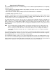
2.0 Introduction This manual describes the functional, mechanical and interface specifications for the following Seagate Constellation® Serial ATA model drives: ST9500530NS ST9160511NS These drives provide the following key features: • 7200 RPM spindle speed. • High instantaneous (burst) data-transfer rates (up to 300 Mbytes per second). • Perpendicular recording technology provides the drives with increased areal density. • State-of-the-art cache and on-the-fly error-correction algorithms.
2.1 About the Serial ATA interface The Serial ATA interface provides several advantages over the traditional (parallel) ATA interface. The primary advantages include: • Easy installation and configuration with true plug-and-play connectivity. It is not necessary to set any jumpers or other configuration options. • Thinner and more flexible cabling for improved enclosure airflow and ease of installation. • Scalability to higher performance levels.
3.0 Drive specifications Unless otherwise noted, all specifications are measured under ambient conditions, at 25°C, and nominal power. For convenience, the phrases the drive and this drive are used throughout this manual to indicate the following drive models: ST9500530NS ST9160511NS Product data communicated in this manual is specific only to the model numbers listed in this manual. The data listed in this manual may not be predictive of future generation specifications or requirements.
Table 1: Drive specification ST9500530NS ST9160511NS Formatted Gbytes (512 bytes/sector)* 500 160 Guaranteed sectors 976,773,168 312,581,808 Heads 6 2 Discs 3 1 Bytes per sector 512 Default sectors per track 63 Default read/write heads 16 Default cylinders 16,383 Recording density, KBPI (kbits/in max) 1410 Track density, KTPI (ktracks/in avg.
Drive specification ST9500530NS ST9160511NS Active 2.6 (typical) 2.5 (typical) Idle** 2.3 (typical) 2.1 (typical) Drive acoustics, sound power (bels) Nonrecoverable read errors 1 sector per 1015 bits read Annualized Failure Rate (AFR) 0.73% Warranty To determine the warranty for a specific drive, use a web browser to access the following web page :http://www.seagate.com/www/en-us/support/warranty_&_returns_assistance From this page, click on the “Verify Your Warranty” link.
3.2 Formatted capacity Model Formatted capacity* Guaranteed sectors ST9500530NS 500 Gbytes 976,773,168 ST9160511NS 160 Gbytes 312,581,808 Bytes per sector 512 *One Gbyte equals one billion bytes when referring to hard drive capacity. Accessible capacity may vary depending on operating environment and formatting. 3.2.1 LBA mode When addressing these drives in LBA mode, all blocks (sectors) are consecutively numbered from 0 to n–1, where n is the number of guaranteed sectors as defined above.
3.5 Physical characteristics Weight: (maximum) ST9500530NS 196 grams (0.43 lbs) ST9160511NS 188 grams (0.41 lbs) Cache buffer Note. 32 Mbytes (32,768 kbytes) Refer to Figure 5, page 23 for detailed mounting configuration dimensions. 3.6 Seek time Seek measurements are taken with nominal power at 25°C ambient temperature. All times are measured using drive diagnostics.
3.8 Power specifications The drive receives DC power (+5V or +12V) through a native SATA power connector. See Figure 4, page 22 on page 22. 3.8.1 Power consumption Power requirements for the drives are listed in the table on page 9. Typical power measurements are based on an average of drives tested, under nominal conditions, using 5.0V and 12.0V input voltage at 25°C ambient temperature.
Parameter Voltage Regulation Average Idle Current Advanced Idle Current Idle_A Idle_B Idle_C Standby Average Sleep Current Maximum Start Current: DC (Peak DC) AC (Peak AC) Delayed Motor Start (DC max) Peak Operating Current (random read): Typical DC Maximum DC Maximum DC (peak) Peak Operating Current (random write): Typical DC Maximum DC Maximum DC (peak) Peak operating current (sequential read): Typical DC Maximum DC Maximum DC (peak) Peak operating current (sequential write): Typical DC Maximum DC Maximum
3.8.1.1 Typical current profiles Figure 1. Typical 5V/12V startup and operation current profile for ST9500530NS Figure 2. Typical 5V/12V startup and operation current profile for ST9160511NS 12 Constellation Serial ATA Product Manual, Rev.
3.8.2 Conducted noise Input noise ripple is measured at the host system power supply across an equivalent 80-ohm resistive load on the +12 volt line or an equivalent 15-ohm resistive load on the +5 volt line. • Using 12-volt power, the drive is expected to operate with a maximum of 120 mV peak-to-peak square-wave injected noise at up to 10 MHz. • Using 5-volt power, the drive is expected to operate with a maximum of 100 mV peak-to-peak square-wave injected noise at up to 10 MHz. Note.
3.8.4 Power-management modes PowerChoiceTM power management Drives using the load/unload architecture provide programmable power management to tailor systems for performance and greater energy efficiency. The table below lists the supported PowerChoice modes. The further you go down in the table, the more power savings you get. For example, Idle_B mode results in greater power savings than Idle_A mode. Standby mode results in the greatest power savings.
3.9 Environmental specifications 3.9.1 Ambient temperature Ambient temperature is defined as the temperature of the environment immediately surrounding the drive. Actual drive case temperature should not exceed 60°C (140°F) within the operating ambient conditions. Above 1,000 feet (305 meters), the maximum temperature is derated linearly to 112°F (44°C) at 10,000 feet (3,048 meters). Operating: 5° to 55°C (41° to 131°F) Nonoperating: –40° to 70°C (–40° to 158°F) 3.9.
3.9.6 Vibration All vibration specifications assume that the drive is mounted securely with the input vibration applied at the drive mounting screws. Vibration may be applied in the X, Y or Z axis. 3.9.6.1 Operating vibration The maximum vibration levels that the drive may experience while meeting the performance standards specified in this document are specified below. 5–22 Hz 0.25 Gs (Limited displacement) 22–350 Hz 0.50 Gs 350–500 Hz 0.25 Gs 3.9.6.
3.10 Acoustics Drive acoustics are measured as overall A-weighted acoustic sound power levels (no pure tones). All measurements are consistent with ISO document 7779. Sound power measurements are taken under essentially free-field conditions over a reflecting plane. For all tests, the drive is oriented with the cover facing upward. Note. For seek mode tests, the drive is placed in seek mode only. The number of seeks per second is defined by the following equation: (Number of seeks per second = 0.
3.12 Reliability 3.12.1 Annualized Failure Rate (AFR) and Mean Time Between Failures (MTBF) The product shall achieve an Annualized Failure Rate - AFR - of 0.73% (Mean Time Between Failures - MTBF - of 1.2 Million hours) when operated in an environment that ensures the HDA case temperatures do not exceed 40°C. Operation at case temperatures outside the specifications in Section 3.9 may increase the product Annualized Failure Rate (decrease MTBF).
Korean RRL If these drives have the Korea Ministry of Information and Communication (MIC) logo, they comply with paragraph 1 of Article 11 of the Electromagnetic Compatibility control Regulation and meet the Electromagnetic Compatibility (EMC) Framework requirements of the Radio Research Laboratory (RRL) Ministry of Information and Communication Republic of Korea. These drives have been tested and comply with the Electromagnetic Interference/Electromagnetic Susceptibility (EMI/EMS) for Class B products.
3.14 Environmental protection Seagate designs its products to meet environmental protection requirements worldwide, including regulations restricting certain chemical substances. 3.14.1 European Union Restriction of Hazardous Substances (RoHS) Directive The European Union Restriction of Hazardous Substances (RoHS) Directive, restricts the presence of chemical substances, including Lead, Cadmium, Mercury, Hexavalent Chromium, PBB and PBDE, in electronic products, effective July 2006.
4.0 Configuring and mounting the drive This section contains the specifications and instructions for configuring and mounting the drive. 4.1 Handling and static-discharge precautions After unpacking, and before installation, the drive may be exposed to potential handling and electrostatic discharge (ESD) hazards.
• Install a SATA host adapter that supports autonegotiation, leave the drive jumper block set to “Normal operation” (see Figure 3, page 22 below), and connect the drive to that adapter. This option has the benefit of not limiting the drive to a 1.5 Gbits/sec transfer rate. 3.0 Gbits per second operation Limit data transfer rate to 1.5 Gbits per second Jumper block SATA power connector SATA interface connector Figure 3. Serial ATA connectors 4.
Note. These dimensions conform to the Small Form Factor Standard documented in SFF-8201 and SFF-8223, found at www.sffcommittee.org. in mm in mm in mm Figure 5. Mounting dimensions—top, side and end view Constellation Serial ATA Product Manual, Rev.
4.5 Cooling Cabinet cooling must be designed by the customer so that the ambient temperature immediately surrounding the drive will not exceed temperature conditions specified in Section 3.9.1, "Ambient temperature." The rack, cabinet, or drawer environment for the drive must provide heat removal from the electronics and head and disc assembly (HDA). You should confirm that adequate heat removal is provided using the temperature measurement guidelines described in Section 3.9.1.
5.0 Serial ATA (SATA) interface These drives use the industry-standard Serial ATA interface that supports FIS data transfers. It supports ATA programmed input/output (PIO) modes 0–4; multiword DMA modes 0–2, and Ultra DMA modes 0–6. For detailed information about the Serial ATA interface, refer to the “Serial ATA: High Speed Serialized AT Attachment” specification. 5.
5.2 Serial ATA device plug connector pin definitions Table 5 summarizes the signals on the Serial ATA interface and power connectors. Table 5: Segment Signal Serial ATA connector pin definitions Pin Function Definition S1 Ground 2nd mate S2 A+ Differential signal pair A from Phy S3 A- S4 Ground 2nd mate S5 B- Differential signal pair B from Phy S6 B+ S7 Ground 2nd mate Key and spacing separate signal and power segments Power P1 V33 3.3V power P2 V33 3.3V power P3 V33 3.
5.3 Supported ATA commands The following table lists Serial ATA standard commands that the drive supports. For a detailed description of the ATA commands, refer to the Serial ATA: High Speed Serialized AT Attachment specification. See “S.M.A.R.T. commands” on page 34.for details and subcommands used in the S.M.A.R.T. implementation.
Command name Command code (in hex) Security Erase Unit F4H Security Freeze F5H Security Set Password F1H Security Unlock F2H Seek 70H Set Features EFH Set Max Address F9H Note: Individual Set Max Address commands are identified by the value placed in the Set Max Features register as defined to the right. Address: Password: Lock: Unlock: Freeze Lock: Set Max Address Extended 37H Set Multiple Mode C6H Sleep E6H S.M.A.R.T. Disable Operations B0H / D9H S.M.A.R.T.
5.3.1 Identify Device command The Identify Device command (command code ECH) transfers information about the drive to the host following power up. The data is organized as a single 512-byte block of data, whose contents are shown in Table 6 on page 27. All reserved bits or words should be set to zero. Parameters listed with an “x” are drive-specific or vary with the state of the drive. See Section 3.0 on page 5 for default parameter settings.
Word Description Value 60–61 Total number of user-addressable LBA sectors available (see Section 3.2 for related information) *Note: The maximum value allowed in this field is: 0FFFFFFFh (268,435,455 sectors, 137 Gbytes). Drives with capacities over 137 Gbytes will have 0FFFFFFFh in this field and the actual number of user-addressable LBAs specified in words 100-103. This is required for drives that support the 48-bit addressing feature.
Word Description Value 108–111 The mandatory value of the world wide name (WWN) for the drive. NOTE: This field is valid if word 84, bit 8 is set to 1 indicating 64-bit WWN support. Each drive will have a unique value. 112–127 ATA-reserved 0000H 128 Security status 0001H 129–159 Seagate-reserved xxxxH 160–254 ATA-reserved 0000H 255 Integrity word xxA5H Note. See the bit descriptions below for words 63, 84, and 88 of the Identify Drive data.
32 Bit Word 88 0 Ultra DMA mode 0 is supported. 1 Ultra DMA mode 1 is supported. 2 Ultra DMA mode 2 is supported. 3 Ultra DMA mode 3 is supported. 4 Ultra DMA mode 4 is supported. 5 Ultra DMA mode 5 is supported. 6 Ultra DMA mode 6 is supported. 8 Ultra DMA mode 0 is currently active. 9 Ultra DMA mode 1 is currently active. 10 Ultra DMA mode 2 is currently active. 11 Ultra DMA mode 3 is currently active. 12 Ultra DMA mode 4 is currently active.
5.3.2 Set Features command This command controls the implementation of various features that the drive supports. When the drive receives this command, it sets BSY, checks the contents of the Features register, clears BSY and generates an interrupt. If the value in the register does not represent a feature that the drive supports, the command is aborted. Power-on default has the read look-ahead and write caching features enabled.
5.3.3 S.M.A.R.T. commands S.M.A.R.T. provides near-term failure prediction for disc drives. When S.M.A.R.T. is enabled, the drive monitors predetermined drive attributes that are susceptible to degradation over time. If self-monitoring determines that a failure is likely, S.M.A.R.T. makes a status report available to the host. Not all failures are predictable. S.M.A.R.T. predictability is limited to the attributes the drive can monitor. For more information on S.M.A.R.T.
Index A ACA 19 acceleration 16 acoustics 17 Agency certification 18 altitude 15 Ambient temperature 15 ambient temperature 9, 10 Annualized Failure Rate (AFR) 18 areal density 3, 8 ATA commands 27 Australia/New Zealand Standard AS/NZS3548 1995 19 Australian Communication Authority (ACA) 19 Australian C-Tick 19 Average latency 9 Average seek time 9 B BPI 8 buffer 9 C cables and connectors 22 cache 9 capacity 8 case temperature 15 CE mark 18 certification 18 Check Power Mode 27 China RoHS directive 20 Class
Information Technology Equipment (ITE) 18 Initialize Device Parameters 27 Input noise ripple 13 input voltage 10 interface 8, 25 internal data-transfer rate OD 8 is 9 ISO document 7779 17 ITE 18 K Korea Ministry of Information and Communication (MIC) 19 Korean RRL 19 L latency 9 LBA mode 8 logical geometry 8 M maintenance 18 master/slave 4 maximum temperature 15 MIC 19 mounting 22 mounting configuration 9 mounting screws 15 mounting the drive 21 N noise 13 nominal power 9 Nonoperating shock 15 Nonoperat
Security Erase Unit 28 Security Freeze 28 Security Set Password 28 Security Unlock 28 Seek 28 Seek time 9 Serial ATA (SATA) interface 25 serial ATA ports 4 Set Features 28 Set Max Address 28 Set Max Address Extended 28 Set Multiple Mode 28 Shock 15 single-track seeks 9 Sleep 28 sound 17 Specification summary table 5 spindle speed 8 Spinup power 10 Standby 28 Standby Immediate 28 Standby mode 10 Standby to Ready 9 Start/stop times 9 start-stop cycles 18 static-discharge 21 support services 1 Surge immunity 1
38 Constellation Serial ATA Product Manual, Rev.
Seagate Technology LLC 920 Disc Drive, Scotts Valley, California 95066-4544, USA Publication Number: 100538694, Rev.