Constellation®.2 SAS Product Manual Standard 512N models ST91000640SS ST9500620SS Self-Encryption 512N models ST91000641SS ST9500621SS SED-FIPS 140-2 models ST91000642SS ST9500622SS 100620418, Rev.
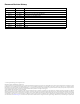
Document Revision History Revision Date Rev. A Rev. B Rev. C Rev. D Rev. E Rev. F Rev. G Rev. H Rev. J Rev. K 06/16/10 07/20/10 10/14/10 02/14/11 03/15/11 04/28/11 08/10/11 04/23/12 09/13/12 04/08/16 Sheets affected or comments Initial release. Trademark revision. fc & 2, 5, 7, 20, 32, 34, 39, 43, 45-46 & 61. 10, 23-24, 29, 31, 36-37 & 53-55. 20, 25 & 40. fc, 2, 5 & 53. 2, 4, 15, 18, 25-26, 39-40, 46, 54, 62 & backcover. fc, 2, 12, 15, 39, 41-42, 50, 54 & 57. 12.
Contents 1.0 Scope . . . . . . . . . . . . . . . . . . . . . . . . . . . . . . . . . . . . . . . . . . . . . . . . . . . . . . . . . . . . . . . . . . . . . . . . . . . . . . . . . . . . . . . 7 2.0 Applicable standards and reference documentation. . . . . . . . . . . . . . . . . . . . . . . . . . . . . . . . . . . . . . . . . . . . 8 2.1 Standards . . . . . . . . . . . . . . . . . . . . . . . . . . . . . . . . . . . . . . . . . . . . . . . . . . . . . . . . . . . . . . . . . . . . . . . . . . . . . . .
6.5 6.6 Environmental limits. . . . . . . . . . . . . . . . . . . . . . . . . . . . . . . . . . . . . . . . . . . . . . . . . . . . . . . . . . . . . . . . . . . . . . . . . 6.5.1 Temperature . . . . . . . . . . . . . . . . . . . . . . . . . . . . . . . . . . . . . . . . . . . . . . . . . . . . . . . . . . . . . . . . . . . . . . 6.5.2 Relative humidity . . . . . . . . . . . . . . . . . . . . . . . . . . . . . . . . . . . . . . . . . . . . . . . . . . . . . . . . . . . . . . . . . 6.5.
11.5 11.6 11.7 11.4.3 Connector requirements . . . . . . . . . . . . . . . . . . . . . . . . . . . . . . . . . . . . . . . . . . . . . . . . . . . . . . . . . . 71 11.4.4 Electrical description . . . . . . . . . . . . . . . . . . . . . . . . . . . . . . . . . . . . . . . . . . . . . . . . . . . . . . . . . . . . . . 71 11.4.5 Pin descriptions . . . . . . . . . . . . . . . . . . . . . . . . . . . . . . . . . . . . . . . . . . . . . . . . . . . . . . . . . . . . . . . . . . . 71 11.4.
List of Figures Figure 1. 1TB model current profiles . . . . . . . . . . . . . . . . . . . . . . . . . . . . . . . . . . . . . . . . . . . . . . . . . . . . . . . . . . . . . . . . . . . . . . . . . . . . . . . . . . . . .32 Figure 2. 500GB model current profiles . . . . . . . . . . . . . . . . . . . . . . . . . . . . . . . . . . . . . . . . . . . . . . . . . . . . . . . . . . . . . . . . . . . . . . . . . . . . . . . . . . .33 Figure 3. 1TB Models (3Gb) DC current and power vs.
Seagate® Technology Support Services For information regarding online support and services, visit: http://www.seagate.com/contacts/ For information regarding Warranty Support, visit: http://www.seagate.com/support/warranty-and-replacements/ For information regarding data recovery services, visit: http://www.seagate.com/services-software/seagate-recoveryservices/recover/ For Seagate OEM, Distribution partner and reseller portals, visit: http://www.seagate.com/partners Constellation.
1.0 Scope This manual describes Seagate Technology® LLC, Constellation.2TM SAS (Serial Attached SCSI) disk drives. Constellation.2 SAS drives support the SAS Protocol specifications to the extent described in this manual. The SAS Interface Manual (part number 100293071) describes the general SAS characteristics of this and other Seagate SAS drives.
2.0 Applicable standards and reference documentation The drives documented in this manual have been developed as system peripherals to the highest standards of design and construction. The drives depends on host equipment to provide adequate power and environment for optimum performance and compliance with applicable industry and governmental regulations. Special attention must be given in the areas of safety, power distribution, shielding, audible noise control, and temperature regulation.
2.1.2 Electromagnetic compliance Seagate uses an independent laboratory to confirm compliance with the directives/standards for CE Marking and CTick Marking. The drive was tested in a representative system for typical applications and comply with the Electromagnetic Interference/Electromagnetic Susceptibility (EMI/EMS) for Class B products. The selected system represents the most popular characteristics for test platforms.
2.1.3 European Union Restriction of Hazardous Substances (RoHS) The European Union Restriction of Hazardous Substances (RoHS) Directive, restricts the presence of chemical substances, including Lead, Cadmium, Mercury, Hexavalent Chromium, PBB and PBDE, in electronic products, effective July 2006. This drive is manufactured with components and materials that comply with the RoHS Directive. A number of parts and materials in Seagate products are procured from external suppliers.
2.2 Reference documents SAS Interface Manual Seagate part number: 100293071 SCSI Commands Reference Manual Seagate part number: 100293068 Self-Encrypting Drives Reference Manual Seagate part number: 100515636 ANSI SAS Documents SFF-8223 SFF-8460 SFF-8470 SFF-8482 ANSI INCITS.xxx ISO/IEC 14776-xxx ISO/IEC 14776-xxx ISO/IEC 14776-xxx 2.
3.0 General description Constellation®.2 drives provide high performance, high capacity data storage for a variety of systems including engineering workstations, network servers, mainframes, and supercomputers. The Serial Attached SCSI interface is designed to meet next-generation computing demands for performance, scalability, flexibility and high-density storage requirements. Constellation®.
3.1 Standard features Constellation®.2 drives have the following standard features: • • • • • • • • • • • • • • • • • • • • • • • • • • • • • • Perpendicular recording technology 1.5 / 3 / 6 Gb Serial Attached SCSI (SAS) interface Integrated dual port SAS controller supporting the SCSI protocol Support for SAS expanders and fanout adapters Firmware downloadable using the SAS interface 128 - deep task set (queue) Supports up to 32 initiators Jumperless configuration.
3.2 Media description The media used on the drive has a glass substrate coated with a thin film magnetic material, overcoated with a proprietary protective layer for improved durability and environmental protection. 3.3 • • • • • • Performance Programmable multi-segmentable cache buffer 600 MB/s maximum instantaneous data transfers. 7200 RPM spindle. Average latency = 4.
3.6 Programmable drive capacity Using the Mode Select command, the drive can change its capacity to something less than maximum. See the Mode Select (6) parameter list table in the SAS Interface Manual, part number 100293071. A value of zero in the Number of Blocks field indicates that the drive will not change the capacity it is currently formatted to have.
4.0 Performance characteristics This section provides detailed information concerning performance-related characteristics and features of Constellation®.2 drives. 4.1 Internal drive characteristics Drive capacity Read/write data heads Bytes per track Bytes per surface Tracks per surface (total) Tracks per inch Peak bits per inch Areal density Internal data rate Disk rotation speed Avg rotational latency 4.
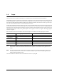
4.2.2 Format command execution time for 512-byte sectors (minutes) 1TB models 500GB models Maximum (with verify) 384 188 Maximum (without verify) 192 94 Execution time measured from receipt of the last byte of the Command Descriptor Block (CDB) to the request for a Status Byte Transfer to the Initiator (excluding connect/disconnect). When changing sector sizes, the format times shown above may need to be increased by 30 minutes. 4.2.
4.4 Prefetch/multi-segmented cache control The drive provides a prefetch (read look-ahead) and multi-segmented cache control algorithms that in many cases can enhance system performance. Cache refers to the drive buffer storage space when it is used in cache operations. To select this feature, the host sends the Mode Select command with the proper values in the applicable bytes in page 08h.
4.5.1 Caching write data Write caching is a write operation by the drive that makes use of a drive buffer storage area where the data to be written to the medium is stored while the drive performs the Write command. If read caching is enabled (RCD=0), then data written to the medium is retained in the cache to be made available for future read cache hits. The same buffer space and segmentation is used as set up for read functions.
5.0 Reliability specifications The following reliability specifications assume correct host and drive operational interface, including all interface timings, power supply voltages, environmental requirements and drive mounting constraints. Seek error rate: Read Error Rates1 Recovered Data Unrecovered Data Miscorrected Data Interface error rate: Mean Time Between Failure (MTBF): Annualized Failure Rate (AFR): Preventive maintenance: 1.
5.1.3 Seek errors A seek error is defined as a failure of the drive to position the heads to the addressed track. After detecting an initial seek error, the drive automatically performs an error recovery process. If the error recovery process fails, a seek positioning error (Error code = 15h or 02h) will be reported with a Hardware error (04h) in the Sense Key. Recoverable seek errors are specified at Less than 10 errors in 108 seeks.
Caution. 5.2.4 The drive motor must come to a complete stop prior to changing the plane of operation. This time is required to insure data integrity. S.M.A.R.T. S.M.A.R.T. is an acronym for Self-Monitoring Analysis and Reporting Technology. This technology is intended to recognize conditions that indicate imminent drive failure and is designed to provide sufficient warning of a failure to allow you to back up the data before an actual failure occurs. Note.
Error rate is the number of errors per operation. The algorithm that S.M.A.R.T. uses to record rates of error is to set thresholds for the number of errors and their interval. If the number of errors exceeds the threshold before the interval expires, the error rate is considered to be unacceptable. If the number of errors does not exceed the threshold before the interval expires, the error rate is considered to be acceptable.
5.2.6 Drive Self Test (DST) Drive Self Test (DST) is a technology designed to recognize drive fault conditions that qualify the drive as a failed unit. DST validates the functionality of the drive at a system level. There are two test coverage options implemented in DST: 1. 2. Extended test Short test The most thorough option is the extended test that performs various tests on the drive and scans every logical block address (LBA) of the drive.
5.2.6.2.2 Invoking DST To invoke DST, submit the Send Diagnostic command with the appropriate Function Code (001b for the short test or 010b for the extended test) in bytes 1, bits 5, 6, and 7. 5.2.6.2.3 Short and extended tests DST has two testing options: 1. 2. short extended These testing options are described in the following two subsections. Each test consists of three segments: an electrical test segment, a servo test segment, and a read/verify scan segment.
5.2.6.2.5 Abort There are several ways to abort a diagnostic. You can use a SCSI Bus Reset or a Bus Device Reset message to abort the diagnostic. You can abort a DST executing in background mode by using the abort code in the DST Function Code field. This will cause a 01 (self-test aborted by the application client) code to appear in the self-test results values log. All other abort mechanisms will be reported as a 02 (self-test routine was interrupted by a reset condition). 5.2.
6.0 Physical/electrical specifications This section provides information relating to the physical and electrical characteristics of the drive. 6.1 PowerChoiceTM power management Drives using the load/unload architecture provide programmable power management to tailor systems for performance and greater energy efficiency. The table below lists the supported PowerChoice modes. The further you go down in the table, the more power savings you get.
6.1.1 PowerChoice reporting methods PowerChoiceTM provides these reporting methods for tracking purposes: Request Sense command reports • Current power condition • Method of entry Note. Processing the Request Sense command does not impact the drive’s power save state.
Table 2: 1000GB drive (Standard & SED model) DC power requirements Parameter Voltage Regulation Average Idle Current Advanced Idle Current Idle1 Idle2 Idle3 Standby Maximum Start Current: DC (Peak DC) 3σ AC (Peak AC) 3σ Delayed Motor Start (DC max) 3σ Peak Operating Current (random read): Typical DC Maximum DC 3σ Maximum DC (peak) 3σ Peak Operating Current (random write): Typical DC Maximum DC 3σ Maximum DC (peak) 3σ Peak operating current (sequential read): Typical DC Maximum DC 3σ Maximum DC (peak) 3σ P
Table 3: 500GB drive (Standard & SED model) DC power requirements Parameter Voltage Regulation Average Idle Current Advanced Idle Current Idle1 Idle2 Idle3 Standby Maximum Start Current: DC (Peak DC) 3σ AC (Peak AC) 3σ Delayed Motor Start (DC max) 3σ Peak Operating Current (random read): Typical DC Maximum DC 3σ Maximum DC (peak) 3σ Peak Operating Current (random write): Typical DC Maximum DC 3σ Maximum DC (peak) 3σ Peak operating current (sequential read): Typical DC Maximum DC 3σ Maximum DC (peak) 3σ Pe
General DC power requirement notes. 1. Minimum current loading for each supply voltage is not less than 1.7% of the maximum operating current shown. 2. The +5V and +12V supplies should employ separate ground returns. 3. Where power is provided to multiple drives from a common supply, careful consideration for individual drive power requirements should be noted. Where multiple units are powered on simultaneously, the peak starting current must be available to each device. 4.
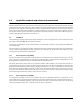
6.3.3 Current profiles The +12V (top) and +5V (bottom) current profiles for the Constellation drives are shown below. Figure 1. 1TB model current profiles Constellation.2 SAS Product Manual, Rev.
Note: All times and currents are typical. See Table 2 and 3 for maximum current requirements. Figure 2. 500GB model current profiles Constellation.2 SAS Product Manual, Rev.
6.4 Power dissipation 1TB model drive in 3Gb operation Please refer to Table 2 for power dissipation numbers. To obtain operating power for typical random read operations, refer to the following I/O rate curve (see Figure 5). Locate the typical I/O rate for a drive in your system on the horizontal axis and read the corresponding +5 volt current, +12 volt current, and total watts on the vertical axis. To calculate BTUs per hour, multiply watts by 3.4123. Figure 3. Note.
1TB model drive in 6Gb operation Please refer to Table 2 for power dissipation numbers. To obtain operating power for typical random read operations, refer to the following I/O rate curve (see Figure 6.). Locate the typical I/O rate for a drive in your system on the horizontal axis and read the corresponding +5 volt current, +12 volt current, and total watts on the vertical axis. To calculate BTUs per hour, multiply watts by 3.4123. Figure 4. 1TB Models (6Gb) DC current and power vs.
500GB model drive in 3Gb operation Please refer to Table 3 for power dissipation numbers. To obtain operating power for typical random read operations, refer to the following I/O rate curve (see Figure 5). Locate the typical I/O rate for a drive in your system on the horizontal axis and read the corresponding +5 volt current, +12 volt current, and total watts on the vertical axis. To calculate BTUs per hour, multiply watts by 3.4123. Figure 5. Note. 500GB Models (3Gb) DC current and power vs.
500GB model drive in 6Gb operation Please refer to Table 3 for power dissipation numbers. To obtain operating power for typical random read operations, refer to the following I/O rate curve (see Figure 6.). Locate the typical I/O rate for a drive in your system on the horizontal axis and read the corresponding +5 volt current, +12 volt current, and total watts on the vertical axis. To calculate BTUs per hour, multiply watts by 3.4123. Figure 6. 500GB Models (6Gb) DC current and power vs.
6.5 Environmental limits Temperature and humidity values experienced by the drive must be such that condensation does not occur on any drive part. Altitude and atmospheric pressure specifications are referenced to a standard day at 58.7°F (14.8°C). Maximum wet bulb temperature is 82°F (28°C). 6.5.1 Temperature a. Operating The drive meets the operating specifications over a 41°F to 140°F (5°C to 60°C) drive case temperature range with a maximum temperature gradient of 36°F (20°C) per hour.
6.5.3 Effective altitude (sea level) a. Operating –200 to +10,000 feet (–61 to +3,048 meters) b. Non-operating –200 to +40,000 feet (–61 to +12,210 meters) 6.5.4 Shock and vibration Shock and vibration limits specified in this document are measured directly on the drive chassis. If the drive is installed in an enclosure to which the stated shock and/or vibration criteria is applied, resonances may occur internally to the enclosure resulting in drive movement in excess of the stated limits.
d. Packaged Seagate finished drive bulk packs are designed and tested to meet or exceed applicable ISTA and ASTM standards. Volume finished drives will be shipped from Seagate factories on pallets to minimize freight costs and ease material handling. Seagate finished drive bulk packs may be shipped individually. For less than full shipments, instructions are printed on the bulk pack carton for minimum drive quantities and proper drive placement. Z X Y Z Y X Figure 8. Note.
6.5.4.2 Vibration a. Operating—normal The drive as installed for normal operation, shall comply with the complete specified performance while subjected to continuous vibration not exceeding 5 - 500 Hz 0.5 Gs Vibration may be applied in the X, Y, or Z axis. Operating normal translational random flat profile 10 - 500 Hz 0.5 GRMS b.
6.5.5 Acoustics Sound power during idle mode shall be 2.2 bels typical when measured to ISO 7779 specification. There will not be any discrete tones more than 10 dB above the masking noise on typical drives when measured according to Seagate specification 30553-001. There will not be any tones more than 24 dB above the masking noise on any drive. 6.5.6 Air cleanliness The drive is designed to operate in a typical office environment with minimal environmental control. 6.5.
6.6 Mechanical specifications Refer to Figure 9 for detailed mounting configuration dimensions. See Section 10.3, “Drive mounting.” Weight: Note. 1TB 500GB 0.44 lb 0.40 lb 0.200 kg 0.183 kg These dimensions conform to the Small Form Factor Standard documented in SFF-8201 and SFF-8223 found at www.sffcommittee.org. in mm in mm in mm Figure 9. Mounting configuration dimensions Constellation.2 SAS Product Manual, Rev.
7.0 About FIPS The Federal Information Processing Standard (FIPS) Publication 140-2 is a U.S. Government Computer Security Standard used to accredit cryptographic modules. It is titled 'Security Requirements for Cryptographic Modules (FIPS PUB 140-2)' and is issued by the National Institute of Standards and Technology (NIST).
Figure 10. Example of FIPS tamper evidence labels. Note. Image is for reference only, may not represent actual drive. Constellation.2 SAS Product Manual, Rev.
8.0 About self-encrypting drives Self-encrypting drives (SEDs) offer encryption and security services for the protection of stored data, commonly known as “protection of data at rest.” These drives are compliant with the Trusted Computing Group (TCG) Enterprise Storage Specifications as detailed in Section 2.2. The Trusted Computing Group (TCG) is an organization sponsored and operated by companies in the computer, storage and digital communications industry.
8.2.2 Locking SP The Locking SP controls read/write access to the media and the cryptographic erase feature. Access to the Locking SP is available using the BandMasterX or EraseMaster passwords. Since the drive owner can define up to 16 data bands on the drive, each data band has its own password called BandMasterX where X is the number of the data band (0 through 15). 8.2.3 Default password When the drive is shipped from the factory, all passwords are set to the value of MSID.
8.6 Cryptographic erase A significant feature of SEDs is the ability to perform a cryptographic erase. This involves the host telling the drive to change the data encryption key for a particular band. Once changed, the data is no longer recoverable since it was written with one key and will be read using a different key. Since the drive overwrites the old key with the new one, and keeps no history of key changes, the user data can never be recovered.
9.0 Defect and error management Seagate continues to use innovative technologies to manage defects and errors. These technologies are designed to increase data integrity, perform drive self-maintenance, and validate proper drive operation. SCSI defect and error management involves drive internal defect/error management and SAS system error considerations (errors in communications between the initiator and the drive).
Table 4 equates the read and write retry count with the maximum possible recovery time for read and write recovery of individual LBAs. The times given do not include time taken to perform reallocations. Reallocations are performed when the ARRE bit (for reads) or AWRE bit (for writes) is one, the RC bit is zero, and the recovery time limit for the command has not yet been met. Time needed to perform reallocation is not counted against the recovery time limit.
9.4 Background Media Scan Background Media Scan (BMS) is a self-initiated media scan. BMS is defined in the T10 document SPC-4 available from the T10 committee. BMS performs sequential reads across the entire pack of the media while the drive is idle. In RAID arrays, BMS allows hot spare drives to be scanned for defects prior to being put into service by the host system. On regular duty drives, if the host system makes use of the BMS Log Page, it can avoid placing data in suspect locations on the media.
9.6 Deferred Auto-Reallocation Deferred Auto-Reallocation (DAR) simplifies reallocation algorithms at the system level by allowing the drive to reallocate unreadable locations on a subsequent write command. Sites are marked for DAR during read operations performed by the drive. When a write command is received for an LBA marked for DAR, the auto-reallocation process is invoked and attempts to rewrite the data to the original location.
9.8.1 Levels of PI There are 4 types of Protection Information. Type 0 - Describes a drive that is not formatted with PI information bytes. This allows for legacy support in non-PI systems. Type 1 - Provides support of PI protection using 10 and 16 byte commands. The RDPROTECT and WRTPROTECT bits allow for checking control through the CDB. Eight bytes of Protection Information are transmitted at LBA boundaries across the interface if RDPROTECT and WRTPROTECT bits are nonzero values.
10.0 Installation Constellation®.2 disk drive installation is a plug-and-play process. There are no jumpers, switches, or terminators on the drive. SAS drives are designed to be used in a host system that provides a SAS-compatible backplane with bays designed to accommodate the drive. In such systems, the host system typically provides a carrier or tray into which you need to mount the drive. Mount the drive to the carrier or tray provided by the host system using four M3 x 0.5 metric screws.
10.2 Cooling Cabinet cooling must be designed by the customer so that the ambient temperature immediately surrounding the drive will not exceed temperature conditions specified in Section 6.5.1, "Temperature." The rack, cabinet, or drawer environment for the drive must provide heat removal from the electronics and head and disk assembly (HDA). You should confirm that adequate heat removal is provided using the temperature measurement guidelines described in Section 6.5.1.
10.3 Drive mounting Mount the drive using the bottom or side mounting holes. If you mount the drive using the bottom holes, ensure that you do not physically distort the drive by attempting to mount it on a stiff, non-flat surface. The allowable mounting surface stiffness is 80 lb/in (14.0 N/mm).
11.0 Interface requirements This section partially describes the interface requirements as implemented on Constellation®.2 drives. Additional information is provided in the SAS Interface Manual (part number 100293071). 11.1 SAS features This section lists the SAS-specific features supported by Constellation®.2 drives. 11.1.1 task management functions Table 5 lists the SAS task management functions supported.
11.2 Dual port support Constellation.2 SAS drives have two independent ports. These ports may be connected in the same or different SCSI domains. Each drive port has a unique SAS address. The two ports have the capability of independent port clocking (e.g. both ports can run at 6Gb/s or the first port can run at 6Gb/s while the second port runs at 3Gb/s. The supported link rates are 1.5, 3.0, or 6.0Gb/s. Subject to buffer availability, the Constellation®.
11.3 SCSI commands supported Table 7 lists the SCSI commands supported by Constellation®.2 drives.
Table 7: Supported commands Command name Command code Supported Last n Deferred Errors or Asynchronous Events page (0Bh) N Last n Error Events page (07h) N Non-medium Error page (06h) Y Pages Supported list (00h) Y Read Error Counter page (03h) Y Read Reverse Error Counter page (04h) N Self-test Results page (10h) Y Start-stop Cycle Counter page (0Eh) Y Temperature page (0Dh) Y Verify Error Counter page (05h) Y Write error counter page (02h) Y Mode Select (same pages as Mode Sense
Table 7: Supported commands Command name Command code Supported Read Capacity (16) 9Eh/10h Y Read Defect Data (10) 37h Y Read Defect Data (12) B7h Y Read Long 3Eh Y (non-SED drives only) Read Long (16) 9Eh/11h Y Reassign Blocks 07h Y Receive Diagnostic Results 1Ch Y Supported Diagnostics pages (00h) Y Translate page (40h) Y Release 17h Y Release (10) 57h Y Report LUNs A0h Y Request Sense 03h Y Actual Retry Count bytes Y Extended Sense Y Field Pointer bytes Y R
Table 7: Supported commands Command name Command code Supported Verify (12) AFh N Verify (16) AFh Y Verify (32) 7Fh/000Ah N Write (6) 0Ah Y Write (10) 2Ah Y DPO bit Y FUA bit Y Write (12) AAh N Write (16) 8Ah Y Write (32) 7Fh/000Bh N Write and Verify (10) 2Eh Y Write and Verify (12) AEh N Write and Verify (16) 8Eh Y Write and Verify (32) 7Fh/000Ch N Write Buffer (modes 0, 2, supported) 3Bh Y (non-SED drives only) Write Buffer 3Bh DPO bit Y Firmware Downloa
11.3.1 Inquiry data Table 8 lists the Inquiry command data that the drive should return to the initiator per the format given in the SAS Interface Manual. Table 8: Constellation®.
before the drive achieves operating speed and is “ready.” An attempt to do so results in a “Check Condition” status. On drives requiring unique saved values, the required unique saved values are stored into the saved values storage location on the media prior to shipping the drive. Some drives may have unique firmware with unique default values also.
Table 9: Mode Sense data changeable and default values for 1TB model drives MODE DATA HEADER: 01 9a 00 10 01 00 00 10 BLOCK DESCRIPTOR: 00 00 00 00 74 70 6d b0 00 00 00 00 00 00 02 00 MODE PAGES: DEF 81 0a c0 14 ff 00 00 00 05 00 ff ff CHG 81 0a ff ff 00 00 00 00 ff 00 ff ff DEF 82 0e 00 00 00 00 00 00 00 00 01 3a 00 00 00 00 CHG 82 0e 00 00 00 00 00 00 00 00 ff ff 00 00 00 00 DEF 83 16 bb d0 00 00 00 00 03 80 04 c4 02 00 00 01 00 ba 00 24 40 00 00 00 CHG 83 16 00 00 00 00 00 00 00 00 00 00 00 00 00 00 00
Table 10: Mode Sense data changeable and default values for 500GB model drives MODE DATA HEADER: 01 9a 00 10 01 00 00 10 BLOCK DESCRIPTOR: 00 00 00 00 3a 38 60 30 00 00 00 00 00 00 02 00 MODE PAGES: DEF 81 0a c0 14 ff 00 00 00 05 00 ff ff CHG 81 0a ff ff 00 00 00 00 ff 00 ff ff DEF 82 0e 00 00 00 00 00 00 00 00 01 3a 00 00 00 00 CHG 82 0e 00 00 00 00 00 00 00 00 ff ff 00 00 00 00 DEF 83 16 bb d0 00 00 00 00 03 80 04 c4 02 00 00 01 00 a8 00 24 40 00 00 00 CHG 83 16 00 00 00 00 00 00 00 00 00 00 00 00 00 00
11.4 Miscellaneous operating features and conditions Table 11 lists various features and conditions. A “Y” in the support column indicates the feature or condition is supported. An “N” in the support column indicates the feature or condition is not supported.
11.4.1 SAS physical interface Figure 13 shows the location of the SAS device connector J1. Figures 14 and 15 provide the dimensions of the SAS connector. Details of the physical, electrical, and logical characteristics are provided within this section. The operational aspects of Seagate’s SAS drives are provided in the SAS Interface Manual. Figure 13. Physical interface Constellation.2 SAS Product Manual, Rev.
0.80 (6X) 5.92 7.62 4.65 0.52 2.00 (3X) 0.45 5.08 0.08 x 45 0.03 (7X) 0.10 M E 42.73 REF. 41.13 0.30 0.15 0.20 B 0.05 (2X) C A B 4.00 1.10 0.08 0.15 D 0.30 CL OF DATUM D 0.05 (4X) A B R0.30 C 0.08 (4X) SEE Detail1 33.43 0.05 B 15.875 15.875 1.27 (14X) 1.27 (6X) 0.84 5.08 0.05 (22X) 0.15 B 4.90 0.08 0.35MIN P15 P1 S7 S1 CL OF DATUM B Figure 14. SAS device plug dimensions Constellation.2 SAS Product Manual, Rev.
Detail A 6.10 S14 2.25 S8 0.05 x 45 (5X) 0.05 0.40 4.85 0.30 0.05 0.10 B 0.05 X 45 (3X) CORING ALLOWED IN THIS AREA. E 4.40 0.15 R0.30 0.08 SEE Detail 2 C 1.95 0.08 A 45 0.35 3.90 0.05 0.15 SECTION C - C SECTION A - A 0.08 0.05 CONTACT SURFACE FLUSH TO DATUM A 0.03 65 1.23 0.08 0.05 0.05 1.90 0.08 30 Detail 2 2.40 0.08 0.10 A SECTION B - B D Figure 15. SAS device plug dimensions (detail) Constellation.2 SAS Product Manual, Rev.
11.4.2 Physical characteristics This section defines physical interface connector. 11.4.3 Connector requirements Contact your preferred connector manufacturer for mating part information. Part numbers for SAS connectors will be provided in a future revision of this publication when production parts are available from major connector manufacturers. The SAS device connector is illustrated in Figures 14 and 15. 11.4.
11.4.6 SAS transmitters and receivers A typical SAS differential copper transmitter and receiver pair is shown in Figure 16. The receiver is AC coupling to eliminate ground shift noise. .01 TX Differential Transfer Medium Transmitter 100 TY Figure 16. SAS transmitters and receivers 11.4.7 Power RX Receiver 100 .01 RY The drive receives power (+5 volts and +12 volts) through the SAS device connector. Three +12 volt pins provide power to the drive, 2 short and 1 long.
The Ready LED Out signal is designed to pull down the cathode of an LED. The anode is attached to the proper +3.3 volt supply through an appropriate current limiting resistor. The LED and the current limiting resistor are external to the drive. See Table 15 for the output characteristics of the LED drive signals. Table 15: LED drive signal State Test condition Output voltage LED off, high 0 V £ VOH £ 3.6 V -100 μA < IOH < 100 μA LED on, low IOL = 15 mA 0 £ VOL £ 0.225 V 11.5.
Seagate Technology LLC AMERICAS Seagate Technology LLC 10200 South De Anza Boulevard, Cupertino, California 95014, United States, 408-658-1000 ASIA/PACIFIC Seagate Singapore International Headquarters Pte. Ltd. 7000 Ang Mo Kio Avenue 5, Singapore 569877, 65-6485-3888 EUROPE, MIDDLE EAST AND AFRICA Seagate Technology SAS 16-18 rue du Dôme, 92100 Boulogne-Billancourt, France, 33 1-4186 10 00 Publication Number: 100620418, Rev.