
User Manual


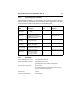


Table Of Contents
- 1.0 Introduction 1
- 2.0 Drive specifications 3
- 2.1 Specification summary table 3
- 2.2 Formatted capacity 6
- 2.3 Default logical geometry 6
- 2.4 Physical organization 6
- 2.5 Recording and interface technology 7
- 2.6 Physical characteristics 7
- 2.7 Seek time 8
- 2.8 Start/stop times 8
- 2.9 Power specifications 8
- 2.10 Environmental specifications 13
- 2.11 Acoustics 16
- 2.12 Electromagnetic immunity 17
- 2.13 Reliability 17
- 2.14 Agency certification 18
- 3.0 Configuring and mounting the drive 21
- 4.0 ATA interface 25
- 5.0 Seagate Technology support services 37
- Figure 1. Typical 5V startup and operation current profile 11
- Figure 2. Typical 12V startup and operation current profile 11
- Figure 3. Master/slave jumper settings 22
- Figure 4. Ultra ATA cable connectors 23
- Figure 5. Mounting dimensions-top, side and end view 24
- Figure 6. I/O pins and supported ATA signals 26
- 1.0 Introduction
- 2.0 Drive specifications
- 2.1 Specification summary table
- 2.2 Formatted capacity
- 2.3 Default logical geometry
- 2.4 Physical organization
- 2.5 Recording and interface technology
- 2.6 Physical characteristics
- 2.7 Seek time
- 2.8 Start/stop times
- 2.9 Power specifications
- 2.10 Environmental specifications
- 2.11 Acoustics
- 2.12 Electromagnetic immunity
- 2.13 Reliability
- 2.14 Agency certification
- 3.0 Configuring and mounting the drive
- 4.0 ATA interface
- 5.0 Seagate Technology support services

12 Barracuda 7200.7 Product Manual, Rev. D
2.9.2 Conducted noise
Input noise ripple is measured at the host system power supply across an
equivalent 80-ohm resistive load on the +12 volt line or an equivalent 15-ohm
resistive load on the +5 volt line.
• Using 12-volt power, the drive is expected to operate with a maximum of 120
mV peak-to-peak square-wave injected noise at up to 10 MHz.
• Using 5-volt power, the drive is expected to operate with a maximum of 100
mV peak-to-peak square-wave injected noise at up to 10 MHz.
Note. Equivalent resistance is calculated by dividing the nominal voltage by
the typical RMS read/write current.
2.9.3 Voltage tolerance
Voltage tolerance (including noise):
2.9.4 Power-management modes
The drive provides programmable power management to provide greater
energy efficiency. In most systems, you can control power management
through the system setup program. The drive features the following power-
management modes:
• Active mode
The drive is in Active mode during the read/write and seek operations.
• Idle mode
The buffer remains enabled, and the drive accepts all commands and returns
to Active mode any time disc access is necessary.
• Standby mode
The drive enters Standby mode when the host sends a Standby Immediate
5V ± 5%
12V ± 10%
Power modes Heads Spindle Buffer
Active Tracking Rotating Enabled
Idle Tracking Rotating Enabled
Standby Parked Stopped Enabled
Sleep Parked Stopped Disabled