
User Manual

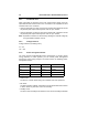


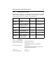


Table Of Contents
- 1.0 Introduction 1
- 2.0 Drive specifications 3
- 2.1 Specification summary table 3
- 2.2 Formatted capacity 6
- 2.3 Default logical geometry 6
- 2.4 Physical organization 6
- 2.5 Recording and interface technology 7
- 2.6 Physical characteristics 7
- 2.7 Seek time 8
- 2.8 Start/stop times 8
- 2.9 Power specifications 8
- 2.10 Environmental specifications 13
- 2.11 Acoustics 16
- 2.12 Electromagnetic immunity 17
- 2.13 Reliability 17
- 2.14 Agency certification 18
- 3.0 Configuring and mounting the drive 21
- 4.0 ATA interface 25
- 5.0 Seagate Technology support services 37
- Figure 1. Typical 5V startup and operation current profile 11
- Figure 2. Typical 12V startup and operation current profile 11
- Figure 3. Master/slave jumper settings 22
- Figure 4. Ultra ATA cable connectors 23
- Figure 5. Mounting dimensions-top, side and end view 24
- Figure 6. I/O pins and supported ATA signals 26
- 1.0 Introduction
- 2.0 Drive specifications
- 2.1 Specification summary table
- 2.2 Formatted capacity
- 2.3 Default logical geometry
- 2.4 Physical organization
- 2.5 Recording and interface technology
- 2.6 Physical characteristics
- 2.7 Seek time
- 2.8 Start/stop times
- 2.9 Power specifications
- 2.10 Environmental specifications
- 2.11 Acoustics
- 2.12 Electromagnetic immunity
- 2.13 Reliability
- 2.14 Agency certification
- 3.0 Configuring and mounting the drive
- 4.0 ATA interface
- 5.0 Seagate Technology support services

Barracuda 7200.7 Product Manual, Rev. D 15
2.10.5 Shock
All shock specifications assume that the drive is mounted securely with the
input shock applied at the drive mounting screws. Shock may be applied in the
X, Y or Z axis.
2.10.5.1 Operating shock
These drives comply with the performance levels specified in this document
when subjected to a maximum operating shock of 63 Gs based on half-sine
shock pulses of 2 msec. Shocks should not be repeated more than two times
per second.
2.10.5.2 Nonoperating shock
The nonoperating shock level that the drive can experience without incurring
physical damage or degradation in performance when subsequently put into
operation is 350 Gs based on a nonrepetitive half-sine shock pulse of 2 msec
duration.
2.10.6 Vibration
All vibration specifications assume that the drive is mounted securely with the
input vibration applied at the drive mounting screws. Vibration may be applied
in the X, Y or Z axis.
2.10.6.1 Operating vibration
The following table lists the maximum vibration levels that the drive may
experience while meeting the performance standards specified in this docu-
ment.
2.10.6.2 Nonoperating vibration
The following table lists the maximum nonoperating vibration that the drive
may experience without incurring physical damage or degradation in perfor-
mance when subsequently put into operation.
5–22 Hz 0.25-inch displacement (zero to peak)
22–350 Hz 0.5 Gs acceleration (zero to peak)
5–22 Hz 1.0-inch displacement (zero to peak)
22–350 Hz 5.0 Gs acceleration (zero to peak)