Product Manual DB35.3 Series 80-160GB ® SATA PATA ST3160215SCE ST3160215ACE ST380215SCE ST380215ACE 100439554 Rev.
Copyright © 2006-2007 Seagate Technology LLC. All rights reserved. Printed in USA Publication number: 100439554, Rev. F August 2007 Seagate, Seagate Technology and the Wave logo are registered trademarks of Seagate Technology LLC in the United States and/or other countries. DB35.3 Series, SeaTools and SeaTDD are either trademarks or registered trademarks of Seagate Technology LLC or one of its affiliated companies in the United States and/or other countries.
Contents 1.0 Introduction. . . . . . . . . . . . . . . . . . . . . . . . . . . . . . . . . . . . . . . . . . . . . . . . . . . . . . . . . . . . . . . . . . . 1 1.1 About the Serial ATA interface . . . . . . . . . . . . . . . . . . . . . . . . . . . . . . . . . . . . . . . . . . . . . . 2 2.0 Drive specifications . . . . . . . . . . . . . . . . . . . . . . . . . . . . . . . . . . . . . . . . . . . . . . . . . . . . . . . . . . . . 3 2.1 Specification summary table . . . . . . . . . . . . . . . . . . . .
ii DB35.3 Series SATA/PATA Product Manual, Rev.
List of Figures Figure 1. Figure 2. Figure 3. Figure 4. Figure 5. Figure 6. Figure 7. Figure 8. Figure 9. Representative 5V startup and operation current profile . . . . . . . . . . . . . . . . . . . . . . . . . . . . . 9 Representative 12V startup and operation current profile . . . . . . . . . . . . . . . . . . . . . . . . . . . . 9 Mounting dimensions for PATA/SATA drives —top, side and end view . . . . . . . . . . . . . . . . . 18 Breather filter hole location . . . . . . . . . . . . . . . . . . . . .
iv DB35.3 Series SATA/PATA Product Manual, Rev.
1.0 Introduction This manual describes the functional, mechanical and interface specifications for the following Seagate® DB35.3® Series SATA/PATA model drives: SATA models PATA models ST3160215SCE ST3160215ACE ST380215SCE ST380215ACE The drives provide the following key features: • 7,200-RPM spindle speed. • Tunneling Magnetoresistive (TMR) recording heads. • Low profile deck design for improved air-flow and low-profile system design.
1.1 About the Serial ATA interface The Serial ATA interface provides several advantages over the traditional Parallel ATA interface. The primary advantages include: • Easy installation and configuration with true plug-and-play connectivity. It is not necessary to set any jumpers or other configuration options. • Thinner and more flexible cabling for improved enclosure airflow and ease of installation. • Scalability to higher performance levels.
2.0 Drive specifications Unless otherwise noted, all specifications are measured under ambient conditions, at 25°C, and nominal power. For convenience, the phrases the drive and this drive are used throughout this manual to indicate the following drive models: SATA models PATA models ST3160215SCE ST3160215ACE ST380215SCE ST380215ACE 2.1 Specification summary table The specifications listed in the table below are for quick reference.
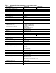
Table 1: 4 Drive specifications summary for 160 and 80 Gbyte models Drive specification ST3160215SCE, ST3160215ACE ST380215SCE, ST380215ACE Formatted Gbytes (512 bytes/sector)* 160 80 Guaranteed sectors 312,581,808 156,301,488 Bytes per sector 512 Default sectors per track 63 Default read/write heads 16 Default cylinders 16,383 Recording density, max 824 kbits/in Track density, max 140 ktracks/in Areal density, max 116.
Drive specification ST3160215SCE, ST3160215ACE ST380215SCE, ST380215ACE Drive acoustics, sound power Idle** 2.6 bels (typical) 2.8 bels (max) CE seek profile 2.7 bels (typical) 2.8 bels (max) Nonrecoverable read errors 1 per 1014 bits read Annualized Failure Rate (AFR)*** 0.68% Warranty 5 years on distribution units. To determine the warranty for a specific drive, use a web browser to access the following web page: www.seagate.
2.1.1 Formatted capacity Model Formatted capacity* Guaranteed sectors Bytes per sector ST3160215SCE, ST3160215ACE 160 Gbytes 312,581,808 512 ST380215SCE, ST380215ACE 80 Gbytes 156,301,488 512 *One Gbyte equals one billion bytes when referring to hard drive capacity. Accessible capacity may vary depending on operating environment and formatting. 2.1.1.
2.1.4 Physical characteristics Drive specification Maximum height (mm) (inches) 20.2 0.794 (mm) (inches) 101.6 4.000 (mm) (inches) 146.6 5.772 Maximum width Maximum length Typical weight 380 grams (0.838 lbs) 160 GB models 370 grams (0.816 lbs) 80 GB models Cache Size 2 Mbytes 2.1.5 Seek time Seek measurements are taken with nominal power at 25°C ambient temperature. All times are measured using drive diagnostics.
2.1.7 Power specifications The drive receives DC power (+5V or +12V) through a four-pin standard drive power connector. 2.1.7.1 Power consumption Power requirements for the drives are listed in the table on page 8. Typical power measurements are based on an average of drives tested, under nominal conditions, using +5.0V and +12.0V input voltage at 25°C ambient temperature. • Spinup power Spinup power is measured from the time of power-on to the time that the drive spindle reaches operating speed.
2.1.7.1.1 Representative current profile Figure 1 Representative 5V startup and operation current profile Figure 2 Representative 12V startup and operation current profile 2.1.7.2 Conducted noise Input noise ripple is measured at the host system power supply across an equivalent 80-ohm resistive load on the +12 volt line or an equivalent 15-ohm resistive load on the +5 volt line.
2.1.7.4 Power-management modes The drive provides programmable power management to provide greater energy efficiency. In most systems, you can control power management through the system setup program.
2.1.8 Environmental specifications 2.1.8.1 Case temperature Actual drive case temperature should not exceed 75°C (167°F). Recommended measurement locations are shown in Figure 3 on page 18. Above 1,000 feet (305 meters), the maximum temperature is derated linearly to 44°C (112°F) at 10,000 feet (3,048 meters). 2.1.8.2 Temperature gradient Operating 20°C per hour (68°F per hour max), without condensation Nonoperating 30°C per hour (86°F per hour max) 2.1.8.3 Humidity 2.1.8.3.
2.1.8.6.1 Operating vibration The following table lists the maximum vibration levels that the drive may experience while meeting the performance standards specified in this document. 5–350 Hz 2.1.8.6.2 0.50 Gs Nonoperating vibration The following table lists the maximum nonoperating vibration that the drive may experience without incurring physical damage or degradation in performance when subsequently put into operation. 5–350 Hz 2.1.9 5.
2.
2.4 Agency certification 2.4.1 Safety certification The drives are recognized in accordance with UL 1950 and CSA C22.2 (950) and meet all applicable sections of IEC950 and EN 60950 as tested by TUV North America. 2.4.2 Electromagnetic compatibility Hard drives that display the CE mark comply with the European Union (EU) requirements specified in the Electromagnetic Compatibility Directive (89/336/EEC).
This equipment is designed to provide reasonable protection against such interference in a residential installation. However, there is no guarantee that interference will not occur in a particular installation. If this equipment does cause interference to radio or television, which can be determined by turning the equipment on and off, you are encouraged to try one or more of the following corrective measures: • Reorient the receiving antenna. • Move the device to one side or the other of the radio or TV.
2.5 Environmental protection Seagate designs its products to meet environmental protection requirements worldwide, including regulations restricting certain chemical substances. 2.5.1 European Union Restriction of Hazardous Substances (RoHS) Directive Seagate designs its products to meet environmental protection requirements worldwide, including regulations restricting certain chemical substances.
3.0 Handling, mounting and configuring the drive This section contains the specifications and instructions for configuring and mounting the drive. 3.1 Handling and static discharge precautions After unpacking, and before installation, the drive may be exposed to potential handling and electrostatic discharge (ESD) hazards.
3.2 Mounting the drive You can mount the drive in any orientation using four screws in the side-mounting holes or four screws in the bottom-mounting holes. See Figure 3 for drive mounting dimensions. Follow these important mounting precautions when mounting the drive: • Allow a minimum clearance of 0.030 inches (0.76 mm) around the entire perimeter of the drive for cooling. • Use only 6-32 UNC mounting screws. • Do not overtighten the mounting screws (maximum torque: 6 inch-lb.).
3.3 Breather filter hole precautions This section contains information regarding the precautions which should be taken regarding the breather filter hole in Seagate hard disc drives. Proper precautions should be taken to ensure full functionality and prevent possible damage to the drive. Breather hole Do not cover or seal this hole. Figure 4 Breather filter hole location Caution: Do not cover, seal, or insert any object into this hole.
3.4 How to configure and attach Serial ATA (SATA) drives 3.4.1 How to configure the drive Each drive on the Serial ATA interface connects point-to-point with the Serial ATA host adapter. There is no master/slave relationship because each drive is considered a master in a point-to-point relationship. If two drives are attached on one Serial ATA host adapter, the host operating system views the two devices as if they were both “masters” on two separate ports.
3.5 How to configure and attach the Parrallel ATA (PATA) drives 3.5.1 How to set the jumper settings The options jumper block shown in Figure 7 is used to configure the drive for operation. It is the 8-pin dual header between the interface connector and the power connector. Use the following settings to configure the drive as a master or a slave. 3.5.1.1 How to configure the drive as a master or slave Master or single drive.
3.5.1.3 Ultra ATA/100 cable An 80-conductor 40-pin cable is required to run Ultra DMA mode 3, mode 4, and mode 5. This cable uses even-numbered conductors connected to the ground pins to improve signal integrity. Master Pin 1 Co Mo mpu the ter rbo ard Slave Figure 8 Note. 22 Note. If you are using a 40-pin, 80-conductor cable, attach the blue connector to the motherboard, the black connector to the master drive, and the gray connector to the slave.
4.0 Interface Interface Refer to SATA Section 4.1 beginning on page 24 PATA Section 4.2 beginning on page 26 The following sections apply to both SATA and PATA drives. • Supported commands (see section 4.3 on page 27) • Identify Device command (see section 4.4 on page 29) • Set Features command (see section 4.5 on page 32) • S.M.A.R.T. commands (see section 4.6 on page 33) DB35.3 Series SATA/PATA Product Manual, Rev.
4.1 Serial ATA (SATA) interface These drives use the industry-standard Serial ATA interface that supports FIS data transfers. It supports ATA programmed input/output (PIO) modes 0–4; multiword DMA modes 0–2, and Ultra DMA modes 0–6. For detailed information about the Serial ATA interface, refer to the “Serial ATA: High Speed Serialized AT Attachment” specification. 4.1.1 Hot-Plug compatibility DB35.
Notes: 1. All pins are in a single row, with a 1.27 mm (0.050”) pitch. 2. The comments on the mating sequence apply to the case of backplane blindmate connector only. In this case, the mating sequences are: • the ground pins P4 and P12. • the pre-charge power pins and the other ground pins. • the signal pins and the rest of the power pins. 3. There are three power pins for each voltage. One pin from each voltage is used for pre-charge when installed in a blind-mate backplane configuration. 4.
4.2 Parallel ATA (PATA) Interface These drives use the industry-standard ATA task file interface that supports 16-bit data transfers. It supports ATA programmed input/output (PIO) modes 0–4; multiword DMA modes 0–2, and Ultra DMA modes 0–5. The drive also supports the use of the IORDY signal to provide reliable high-speed data transfers. You can use a daisy-chain cable to connect two drives to a single AT host bus.
4.3 Supported ATA commands The following table lists ATA-standard commands that the drive supports. For a detailed description of the ATA commands, refer to the Serial ATA: High Speed Serialized AT Attachment specification for SATA models or the Draft ATA-7 Standard for the PATA models. See “S.M.A.R.T. commands” on page 33 for details and subcommands used in the S.M.A.R.T. implementation.
Command name Command code (in hex) Security Erase Prepare F3H Security Erase Unit F4H Security Freeze F5H Security Set Password F1H Security Unlock F2H Seek 70H Set Features EFH Set Max Address F9H Note: Individual Set Max Address commands are identified by the value placed in the Set Max Features register as defined to the right. Address: Password: Lock: Unlock: Freeze Lock: Set Max Address Extended 37H Set Multiple Mode C6H Sleep 99H or E6H S.M.A.R.T.
4.4 Identify Device command The Identify Device command (command code ECH) transfers information about the drive to the host following power up. The data is organized as a single 512-byte block of data, whose contents are shown in the Table 6 on page 27. All reserved bits or words should be set to zero. Parameters listed with an “x” are drive-specific or vary with the state of the drive. See Section 2.0 on page 3 for default parameter settings.
Word Description Value 60–61 Total number of user-addressable LBA sectors available (see Section 2.1.1 for related information) *Note: The maximum value allowed in this field is: 0FFFFFFFh (268,435,455 sectors, 137 Gbytes). Drives with capacities over 137 Gbytes will have 0FFFFFFFh in this field and the actual number of user-addressable LBAs specified in words 100-103. This is required for drives that support the 48-bit addressing feature.
Word Description Value 128 Security status 0001H 129–159 Seagate-reserved xxxxH 160–254 ATA-reserved 0000H 255 Integrity word xxA5H Note. Advanced Power Management (APM) and Automatic Acoustic Management (AAM) features are not supported Note. See the bit descriptions below for words 63, 88, and 93 of the Identify Drive data: Description (if bit is set to 1) Bit Word 63 0 Multiword DMA mode 0 is supported. 1 Multiword DMA mode 1 is supported. 2 Multiword DMA mode 2 is supported.
4.5 Set Features command This command controls the implementation of various features that the drive supports. When the drive receives this command, it sets BSY, checks the contents of the Features register, clears BSY and generates an interrupt. If the value in the register does not represent a feature that the drive supports, the command is aborted. Power-on default has the read look-ahead and write caching features enabled.
4.6 S.M.A.R.T. commands S.M.A.R.T. provides near-term failure prediction for disc drives. When S.M.A.R.T. is enabled, the drive monitors predetermined drive attributes that are susceptible to degradation over time. If self-monitoring determines that a failure is likely, S.M.A.R.T. makes a status report available to the host. Not all failures are predictable. S.M.A.R.T. predictability is limited to the attributes the drive can monitor. For more information on S.M.A.R.T.
34 DB35.3 Series SATA/PATA Product Manual, Rev.
5.0 Seagate Technology support services Internet For information regarding Seagate products and services, visit www.seagate.com. Worldwide support is available 24 hours daily by email for your questions. Presales Support: Presales@Seagate.com Technical Support: DiscSupport@Seagate.com Warranty Support: http://www.seagate.com/support/service/index.html mySeagate my.seagate.com is the industry's first Web portal designed specifically for OEMs and distributors.
Customer Service Operations Warranty Service Seagate offers worldwide customer support for Seagate products. Seagate distributors, OEMs and other direct customers should contact their Seagate Customer Service Operations (CSO) representative for warrantyrelated issues. Resellers or end users of drive products should contact their place of purchase or Seagate warranty service for assistance. Have your serial number and model or part number available.
Index A acoustics 12 Active mode 10 agency certification (regulatory) 14 altitude 11 ambient conditions 3 areal density 6 ATA-standard commands 27 Australian C-Tick 14 autodetection 1 average seek time 7 B BPI 6 breather filter hole precautions 19 burst 1 C cable 22 cable select 1 cables and connectors 20 cable-select option 21 cache 1 case temperature 11 CE mark 14 certification 14 Check Power Mode 27 China RoHS directive 16 commands 27 compliance 14 conducted noise 9 conducted RF immunity 13 configuring
Identify Device command 29 Idle 27 Idle and Standby timers 10 Idle Immediate 27 Idle mode 10 Idle mode power 8 IEC950 14 Information Technology Equipment 14 Initialize Device Parameters 27 interface 6, 23 interface signals 26 interference 14 internal data-transfer rate OD 6 ISO document 7779 12 physical characteristics 7 pins 26 PIO 26 point-to-point 2, 20 power consumption 8 power management 10 power specifications 8 power-management modes 10 Power-on to Ready 7 precautions 18 preventive maintenance 13 pr
S.M.A.R.T. Execute Offline 28 S.M.A.R.T. Read Attribute Thresholds 28 S.M.A.R.T. Read Data 28 S.M.A.R.T. Read Log Sector 28 S.M.A.R.T. Return Status 28 S.M.A.R.T. Save Attribute Values 28 S.M.A.R.T.
40 DB35.3 Series SATA/PATA Product Manual, Rev.
Seagate Technology LLC 920 Disc Drive, Scotts Valley, California 95066-4544, USA Publication Number: 100439554, Rev. F, Printed in U.S.A.