............................................. U Series CE Family ............................................. ST380020ACE, ST360020ACE ............................................. ST340810ACE, ST320410ACE ............................................. Ultra ATA Interface Drives ............................................. Product Manual .............................................
............................................. U Series CE Family ............................................ ST380020ACE, ST360020ACE ............................................. ST340810ACE, ST320410ACE ............................................. Ultra ATA Interface Drives ............................................. Product Manual .............................................
2001 Seagate Technology LLC All rights reserved Publication Number: 100140718, Rev. A, July 2001 Seagate, Seagate Technology and the Seagate logo are registered trademarks of Seagate Technology LLC. SeaShield, SeaShell and U Series CE are either registered trademarks or trademarks of Seagate Technology LLC. Other product names are registered trademarks or trademarks of their owners. Seagate reserves the right to change, without notice, product offerings or specifications.
U Series CE Family Product Manual, Rev. A iii Contents Introduction . . . . . . . . . . . . . . . . . . . . . . . . . . . . . . . . . . . . . . . . . . . 1 Specification summary table . . . . . . . . . . . . . . . . . . . . . . . . . . . . . . 2 1.0 Drive specifications . . . . . . . . . . . . . . . . . . . . . . . . . . . . . . . . . 5 1.1 Formatted capacity . . . . . . . . . . . . . . . . . . . . . . . . . . . . . . . . . 5 1.1.1 Default logical geometry . . . . . . . . . . . . . . . . . . . . . . . . .
iv U Series CE Family Product Manual, Rev. A 1.12.3 FCC verification . . . . . . . . . . . . . . . . . . . . . . . . . . . . . 16 2.0 Configuring and mounting the drive . . . . . . . . . . . . . . . . . . . 17 2.1 Handling and static-discharge precautions . . . . . . . . . . . . . . 17 2.2 Jumper settings . . . . . . . . . . . . . . . . . . . . . . . . . . . . . . . . . . 18 2.2.1 Master/slave configuration . . . . . . . . . . . . . . . . . . . . . . 18 2.2.2 Cable-select option . . . . . . . . . . . . .
U Series CE Family Product Manual, Rev. A v Figures Figure 1. Typical startup and operation current profile . . . . . . . . . . . . 9 Figure 2. Master/slave jumper settings . . . . . . . . . . . . . . . . . . . . . . . 18 Figure 3. Mounting dimensions—top, side and end view . . . . . . . . . 20 Figure 4. I/O pins and supported ATA signals. . . . . . . . . . . . . . . . . .
vi U Series CE Family Product Manual, Rev.
U Series CE Family Product Manual, Rev. A 1 Introduction This manual describes the functional, mechanical and interface specifications for the ST380020ACE, ST360020ACE, ST340810ACE and the ST320410ACE. These drives provide the following key features: • 8.
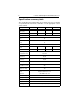
2 U Series CE Family Product Manual, Rev. A Specification summary table The specifications listed in this table are for quick reference. For details on specification measurement or definition, see the appropriate section of this manual.
U Series CE Family Product Manual, Rev. A Drive Specification ST380020ACE ST360020ACE ST340810ACE ST320410ACE Track-to-track seek time (msec typical) 1.2 (read) 2.0 (write) Average seek time (msec typical) 8.9 Average seek read (msec typical) 9.9 Average seek write (msec typical) 10.9 Full-stroke seek time (msec typical) Average latency (msec) 22.0 (read) 24.0 (write) 5.55 msec Power-on to ready (sec typical) 6.5 sec Standby to ready (sec typical) 6.
4 U Series CE Family Product Manual, Rev. A Drive Specification ST380020ACE ST360020ACE ST340810ACE ST320410ACE Altitude (meters below mean sea level, max) –121.92 m to 12,192 m (–400 ft to 40,000+ ft) Shock, operating (Gs max at 2 msec) 63 Gs Shock, nonoperating (Gs max at 1 and 2 msec) 350 Gs Vibration, operating 0.5 Gs (0 to peak, 22–350 Hz) Vibration, nonoperating Drive acoustics Sound power in bels Idle mode Performance Seek Nonrecoverable read errors 5 Gs (0 to peak, 22–350 Hz) 2.
U Series CE Family Product Manual, Rev. A 5 1.0 Drive specifications Unless otherwise noted, all specifications are measured under ambient conditions, at 25°C, and nominal power. For convenience, the phrases the drive and this drive are used throughout this manual to indicate the ST380020ACE, ST360010ACE, ST340810ACE and the ST320410ACE. 1.
6 U Series CE Family Product Manual, Rev. A 1.2 Physical organization Drive Model Read/Write heads (GMR) Number of discs ST380020ACE 4 2 ST360020ACE 3 2 ST340810ACE 2 1 ST320410ACE 1 1 1.3 Recording and interface technology Interface ATA Recording method 96/102 GPRML Recording density BPI (bits/inch) 562,436 Track density TPI (tracks/inch) 58,000 Areal density (Mbits/inch2 max) 32,622 Spindle speed (RPM) (± 0.
U Series CE Family Product Manual, Rev. A 7 1.5 Seek time Seek measurements are taken with nominal power at 25°C ambient temperature. All times are measured using drive diagnostics. The specifications in the table below are defined as follows: • Track-to-track seek time is an average of all possible single-track seeks in both directions. • Average seek time is a true statistical random average of at least 5,000 measurements of seeks between random tracks, less overhead.
8 U Series CE Family Product Manual, Rev. A 1.7 Power specifications The drive receives DC power (+5V or +12V) through a four-pin standard drive power connector. 1.7.1 Power consumption Power requirements for the drives are listed in the table on page 9. Typical power measurements are based on an average of drives tested, under nominal conditions, using 5.0V input voltage at 25°C ambient temperature.
U Series CE Family Product Manual, Rev. A 9 Typical Amps Means Power Mode Typical Watts 5V 12V — 0.75 2.5 Seek (Random, no read/write) Performance mode 7.5 0.83 0.279 Operating (read/write) Performance mode 7.5 0.94 0.233 Idle 5.0 0.63 0.154 Standby 1.2 0.2 0.017 Sleep 0.9 0.15 0.0125 Spinup 1.7.1.1 Typical current profile Current (amps) 2.0 1.5 1.0 0.5 0 -0.5 -1.0 -1.5 -2.0 1 2 3 4 5 6 7 Time (seconds) Figure 1.
10 U Series CE Family Product Manual, Rev. A 1.7.2 Conducted noise Input noise ripple is measured at the host system power supply across an equivalent 80-ohm resistive load on the +12 volt line or an equivalent 15-ohm resistive load on the +5 volt line. • Using 12-volt power, the drive is expected to operate with a maximum of 120 mV peak-to-peak square-wave injected noise at up to 10 MHz.
U Series CE Family Product Manual, Rev. A 11 established using a Standby or Idle command. In Standby mode, the drive buffer is enabled, the heads are parked and the spindle is at rest. The drive accepts all commands and returns to Active mode any time disc access is necessary. • Sleep mode The drive enters Sleep mode after receiving a Sleep command from the host. In Sleep mode, the drive buffer is disabled, the heads are parked and the spindle is at rest.
12 U Series CE Family Product Manual, Rev. A 1.8.3 Humidity 1.8.3.1 Relative Humidity Operating 5% to 90% noncondensing (30% per hour max) Nonoperating 5% to 95% noncondensing (30% per hour max) 1.8.3.2 Wet bulb temperature Operating 29.4°C (84°F) max Nonoperating 40.0°C (104°F) max 1.8.4 Altitude Operating –60.96 m to 3,048 m (–200 ft to 10,000+ ft) Nonoperating –121.92 m to 12,192 m (–400 ft to 40,000+ ft) 1.8.
U Series CE Family Product Manual, Rev. A 13 1.8.6.1 Operating vibration The following table lists the maximum vibration levels that the drive may experience while meeting the performance standards specified in this document. 5–21 Hz 0.02-inch displacement (peak to peak) 22–350 Hz 0.5 Gs acceleration (zero to peak) 351–500 Hz 0.25 Gs acceleration (zero to peak) 1.8.6.
14 U Series CE Family Product Manual, Rev. A 1.
U Series CE Family Product Manual, Rev. A 15 1.12.2 Electromagnetic compatibility Hard drives that display the CE mark comply with the European Union (EU) requirements specified in the Electromagnetic Compatibility Directive (89/336/EEC). Testing is performed to the levels specified by the product standards for Information Technology Equipment (ITE). Emission levels are defined by EN 55022, Class B and the immunity levels are defined by EN 55024.
16 U Series CE Family Product Manual, Rev. A Australian C-Tick (N176) If these models have the C-Tick marking, they comply with the Australia/ New Zealand Standard AS/NZS3548 1995 and meet the Electromagnetic Compatibility (EMC) Framework requirements of the Australian Communication Authority (ACA). 1.12.3 FCC verification These drives are intended to be contained solely within a personal computer or similar enclosure (not attached as an external device).
U Series CE Family Product Manual, Rev. A 17 2.0 Configuring and mounting the drive This section contains the specifications and instructions for configuring and mounting the drive. 2.1 Handling and static-discharge precautions After unpacking, and before installation, the drive may be exposed to potential handling and electrostatic discharge (ESD) hazards. Observe the following standard handling and static-discharge precautions: Caution: • The SeaShell™ replaces electrostatic discharge (ESD) bags.
18 U Series CE Family Product Manual, Rev. A 2.2 Jumper settings 2.2.1 Master/slave configuration The options jumper block shown in Figure 2 is used to configure the drive for operation. It is the 8-pin dual header between the interface connector and the power connector. Use the following settings to configure the drive as a master or a slave. Master or single drive. The drive is configured at the factory for a master or single-drive operation with a jumper set on pins 7 and 8. Drive as slave.
U Series CE Family Product Manual, Rev. A 19 2.2.2 Cable-select option Computers that use cable-select determine the master and slave drives by selecting or deselecting pin 28, CSEL, on the interface bus. Master and slave drives are determined by their physical position on the cable. To enable cable select, set a jumper on pins 5 and 6 as shown in Figure 2 on page 18. Refer to your computer manual to determine whether your computer supports this option. 2.2.
20 U Series CE Family Product Manual, Rev. A 2.1 Drive mounting You can mount the drive in any orientation using four screws in the sidemounting holes or four screws in the bottom-mounting holes. See Figure 3 for drive mounting dimensions. Follow these important mounting precautions when mounting the drive: • Allow a minimum clearance of 0.030 inches (0.76 mm) around the entire perimeter of the drive for cooling. • Use only 6-32 UNC mounting screws. Insert the screws no more than 0.20 inch (5.
U Series CE Family Product Manual, Rev. A 21 3.0 ATA interface These drives use the industry-standard ATA task file interface that supports 16-bit data transfers. It supports ATA programmed input/output (PIO) modes 0–4; multiword DMA modes 0–2, and Ultra DMA modes 0–5. The drive also supports the use of the IORDY signal to provide reliable high-speed data transfers. You can use a daisy-chain cable to connect two drives to a single AT host bus.
22 U Series CE Family Product Manual, Rev.
U Series CE Family Product Manual, Rev. A 23 3.1.1 Supported ATA commands The following table lists ATA-standard commands that the drive supports. For a detailed description of the ATA commands, refer to the Draft ATA-Rev 6 Standard. See Section 3.1.4 on page 31 for details and subcommands used in the S.M.A.R.T. implementation.
24 U Series CE Family Product Manual, Rev. A Command name Command code (in hex) Write Multiple C5H Write Sectors 30H, 31H ATA-standard power-management commands Check Power Mode 98H or E5H Idle 97H or E3H Idle Immediate 95H or E1H Sleep 99H or E6H Standby 96H or E2H Standby Immediate 94H or E0H ATA-standard security commands Security Set Password F1H Security Unlock F2H Security Erase Prepare F3H Security Erase Unit F4H Security Freeze Lock F5H Security Disable Password F6H 3.
U Series CE Family Product Manual, Rev.
26 U Series CE Family Product Manual, Rev.
U Series CE Family Product Manual, Rev.
28 U Series CE Family Product Manual, Rev. A Word Description Value 92 Master Password Revision code FFFEH 93 Hardware Reset Value (see description following this table) xxxxH 94 Auto Acoustic Management Setting xxxxH 95–127 ATA-reserved 0000H 128 Security Status 0001H 129– 159 Seagate-reserved xxxxH 160– 254 ATA-reserved 0000H 255 Integrity word xxA5H Note.
U Series CE Family Product Manual, Rev. A 3 Ultra DMA mode 3 is supported. 4 Ultra DMA mode 4 is supported. 5 Ultra DMA mode 5 is supported. 8 Ultra DMA mode 0 is currently active. 9 Ultra DMA mode 1 is currently active. 10 Ultra DMA mode 2 is currently active. 11 Ultra DMA mode 3 is currently active. 12 Ultra DMA mode 4 is currently active. 13 Ultra DMA mode 5 is currently active.
30 U Series CE Family Product Manual, Rev. A 09H PIO mode 1 0AH PIO mode 2 0BH PIO mode 3 0CH PIO mode 4 (default) 20H Multiword DMA mode 0 21H Multiword DMA mode 1 22H Multiword DMA mode 2 40H Ultra DMA mode 0 41H Ultra DMA mode 1 42H Ultra DMA mode 2 43H Ultra DMA mode 3 44H Ultra DMA mode 4 45H Ultra DMA mode 5 05H Enable advanced power management. 42H Auto Acoustic Management FEH Performance Seek 80H Quiet Acoustic Seek 55H Disable read look-ahead (read cache) feature. 82H Disable write cache.
U Series CE Family Product Manual, Rev. A 31 3.1.4 S.M.A.R.T. commands S.M.A.R.T. provides near-term failure prediction for disc drives. When S.M.A.R.T. is enabled, the drive monitors predetermined drive attributes that are susceptible to degradation over time. If self-monitoring determines that a failure is likely, S.M.A.R.T. makes a status report available to the host. Not all failures are predictable. S.M.A.R.T. predictability is limited to the attributes the drive can monitor.
32 U Series CE Family Product Manual, Rev.
U Series CE Family Product Manual, Rev.
34 U Series CE Family Product Manual, Rev.
U Series CE Family Product Manual, Rev.
36 U Series CE Family Product Manual, Rev. A Seagate Technology LLC 920 Disc Drive, Scotts Valley, California 95066, USA Publication Number: 100140718, Rev.