Laptop Thin HDD 5400 RPM - Product Manual Standard models Self-Encrypting Drive models ST500LT012 ST320LT012 ST250LT012 ST500LT025 ST320LT025 ST250LT025 Standard models w/ZGS SED (FIPS 140-2) models ST500LT034 ST320LT032 ST250LT028 ST500LT015 ST320LT015 ST250LT015 100713732, Rev. R Gen 9.
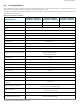
Document Revision History Revision Date Pages affected Rev. A 01/18/2013 Initial release. Rev. B 02/05/2013 2, 4-7 & 10. Rev. C 03/05/2013 1 & 17-18. Rev. D 04/12/2013 4, 6 & 17. Rev. E 07/25/2013 4-6, 12, 17 & 18. Rev. F 09/04/2013 fc & 2. Rev. G 11/06/2013 2, 20-21 & 24-26. Rev. H 05/08/2014 below, 3, 5, 11-12, 14-15, 17-18 & 30. Rev. J 06/11/2014 fc, 2, 10, 16 & 22. Rev. K 11/07/2014 5 & 12. Rev.
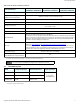
Contents Seagate® Technology Support Services . . . . . . . . . . . . . . . . . . . . . . . . . . . . . . . . . . . . . . . . . . . . . . . . . . . . . . . . . . . . . . . . . .5 1.0 Introduction . . . . . . . . . . . . . . . . . . . . . . . . . . . . . . . . . . . . . . . . . . . . . . . . . . . . . . . . . . . . . . . . . . . . . . . . . . . . . . . . . . . . . . . . . . .6 1.1 About the Serial ATA Interface . . . . . . . . . . . . . . . . . . . . . . . . . . . . . . . . . . . . . . . . . . . . . . . .
Contents 3.0 Configuring and Mounting the Drive . . . . . . . . . . . . . . . . . . . . . . . . . . . . . . . . . . . . . . . . . . . . . . . . . . . . . . . . . . . . . . . . . . 20 3.1 Handling and Static-Discharge Precautions . . . . . . . . . . . . . . . . . . . . . . . . . . . . . . . . . . . . . . . . . . . . . . . . . . . . . . . . . . . . . 20 3.2 Configuring the Drive . . . . . . . . . . . . . . . . . . . . . . . . . . . . . . . . . . . . . . . . . . . . . . . . . . . . . . . . . . . . . . . . .
Figures Figure 1 Figure 2 Figure 3 Figure 4 Figure 5 Typical 5V Startup and Operation Current Profile . . . . . . . . . . . . . . . . . . . . . . . . . . . . . . . . . . . . . . . . . . . . . . . . . . . . . . . . . . . . . . . . . . . . . . . . . Attaching SATA Cabling . . . . . . . . . . . . . . . . . . . . . . . . . . . . . . . . . . . . . . . . . . . . . . . . . . . . . . . . . . . . . . . . . . . . . . . . . . . . . . . . . . . . . . . . . . . . . . . . . Mounting Dimensions (for standard models). .
Seagate® Technology Support Services For information regarding online support and services, visit: http://www.seagate.com/contacts/ For information regarding Warranty Support, visit: http://www.seagate.com/support/warranty-and-replacements/ For information regarding data recovery services, visit: http://www.seagate.com/services-software/data-recovery-services/ For Seagate OEM, Distribution partner and reseller portals, visit: http://www.seagate.com/partners/ Seagate Laptop Thin HDD Product Manual, Rev.
1.
1.1 About the Serial ATA Interface The Serial ATA interface provides several advantages over the traditional (parallel) ATA interface. The primary advantages include: Easy installation and configuration with true plug-and-play connectivity. It is not necessary to set any jumpers or other configuration options. Thinner and more flexible cabling for improved enclosure airflow and ease of installation. Scalability to higher performance levels.
Drive Specifications 2.0 Drive Specifications Unless otherwise noted, all specifications are measured under ambient conditions, at 25°C, and nominal power. For convenience, the phrases the drive and this drive are used throughout this manual to indicate the following drive models: The specification summaries listed in the following tables are for quick reference. For details on specification measurement or definition, refer to the appropriate section of this manual.
Drive Specifications Table 1: Drive Specifications Summary (continued) Drive Specification ST500LT012, ST500LT015 ST500LT025, ST500LT034 Altitude, operating ST320LT012, ST320LT015 ST320LT025, ST320LT032 ST250LT012, ST250LT015 ST250LT025, ST250LT028 –304.8 m to 3048 m (–1000 ft to 10,000+ ft) Altitude, nonoperating (below mean sea level, max) –304.8 m to 12,192 m (–1000 ft to 40,000+ ft) Operational Shock 400 Gs at 2 ms max Non-Operational Shock 1000 Gs at 1 ms max 5–200 Hz: 2.
Drive Specifications 2.1.1 LBA mode When addressing these drives in LBA mode, all blocks (sectors) are consecutively numbered from 0 to n–1, where n is the number of guaranteed sectors as defined above. Refer to Configuring and Mounting the Drive on page 20 (words 60-61 and 100-103) for additional information about 48-bit addressing support of drives with capacities over 137 GB. 2.
Drive Specifications 2.5 Seek time Seek measurements are taken with nominal power at 25°C ambient temperature. All times are measured using drive diagnostics. The specifications in the table below are defined as follows: Track-to-track seek time is an average of all possible single-track seeks in both directions. Average seek time is a true statistical random average of at least 5000 measurements of seeks between random tracks, less overhead.
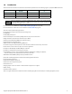
Drive Specifications Table 4: DC Power Requirements Power Dissipation 1. 2. +5V input average (25° C) Spinup (max) 1.00A Seek average 1.40W Write average 1.70W Read average 1.30W Idle, performance (1) 1.20W Idle, active 0.70W Idle, low power mode 0.45W Standby(2) 0.18W Sleep 0.18W During periods of drive idle, some offline activity may occur according to the S.M.A.R.T. specification, which may increase acoustic and power to operational levels.
Drive Specifications 2.7.2 Conducted noise Input noise ripple is measured at the host system power supply across an equivalent 15-ohm resistive load on the +5 volt line. Using 5-volt power, the drive is expected to operate with a maximum of 100 mV peak-to-peak square-wave injected noise at up to 20 MHz. Note 2.7.3 Equivalent resistance is calculated by dividing the nominal voltage by the typical RMS read/write current. Voltage tolerance Voltage tolerance (including noise): +5V ± 5% 2.7.
Drive Specifications 2.8 Environmental Specifications This section provides the temperature, humidity, shock, and vibration specifications for Laptop Thin drives. Ambient temperature is defined as the temperature of the environment immediately surrounding the drive. Above 1000 feet (305 meters), the maximum temperature is derated linearly by 1°C every 1000 feet.
Drive Specifications 2.8.2 Vibration All vibration specifications assume that the drive is mounted securely with the input vibration applied at the drive mounting screws. Vibration may be applied in the X, Y, or Z axis. 2.8.2.1 Operating vibration The maximum vibration levels that the drive may experience while meeting the performance standards specified in this document are specified below. 5–200 Hz 2.0 Gs (0 to peak). Max displacement may apply below 10 Hz. 201–500 Hz 1.0 Gs (0 to peak). 2.8.2.
Drive Specifications 2.10 Electromagnetic Immunity When properly installed in a representative host system, the drive operates without errors or degradation in performance when subjected to the radio frequency (RF) environment as defined in Table 7:.
Drive Specifications 2.11 Reliability Nonrecoverable read errors 1 per 1014 bits read, max Load/Unload (U/UL) 25°C, 50% relative humidity 600,000 software-controlled power on/off cycles 20,000 hard power on/off cycles Rated workload Average annualized workload rating: <55 TB/year. The specifications for the product assumes the I/O workload does not exceed the average annualized workload rate limit of 55 TB/year.
Drive Specifications Australian RCM If these models have the RCM marking, they comply with the Australia/New Zealand Standard AS/NZS CISPR22: 2009, and meet the Electromagnetic Compatibility (EMC) Framework requirements of the Australian Communications and Media Authority (ACMA). 2.12.3 FCC verification These drives are intended to be contained solely within a personal computer or similar enclosure (not attached as an external device).
2.13.2 China Requirements — China RoHS 2 China RoHS 2 refers to the Ministry of Industry and Information Technology Order No. 32, effective July 1, 2016, titled Management Methods for the Restriction of the Use of Hazardous Substances in Electrical and Electronic Products.
Configuring and Mounting 3.0 Configuring and Mounting the Drive This section contains the specifications and instructions for configuring and mounting the drive. 3.1 Handling and Static-Discharge Precautions After unpacking, and before installation, the drive may be exposed to potential handling and electrostatic discharge (ESD) hazards. Observe the following standard handling and static-discharge precautions. CAUTION 3.
3.3 Drive Mounting Users can mount the drive in any orientation using four screws in the side-mounting holes or four screws in the bottom-mounting holes. Refer to Figure 3 for drive mounting dimensions. Follow these important mounting precautions when mounting the drive: Allow a minimum clearance of 0.030 in (0.76 mm) around the entire perimeter of the drive for cooling. Use only M3 x 0.5 mounting screws. Do not overtighten the mounting screws. Maximum torque: 4.0 in-lb (0.4519 N-m).
Configuring and Mounting Figure 4 Mounting dimensions (for FIPS 140-2 models) 3.951 +.008 / -.010 in 100.36 +.203 / -.25 mm .835 ± .010 in 21.21 ± .25 mm .334 ± .050 in 8.48 ± 1.27 mm .324 ± .010 in 8.23 ± .25 mm BREATHER HOLE, DO NOT COVER OR SEAL 2.750 ± .010 in 69.85 ± .25 mm .551 in 13.99 mm 0.268 ± .008 in 6.81 ± .203 mm 3.567 in 90.60 mm Do Not Remove * Tamper Indicator * C 2X .118 in 2.99 mm BOTH SIDES .230 in 5.84 mm .263 in 6.68 mm .551 in 13.
About FIPS 4.0 About FIPS The Federal Information Processing Standard (FIPS) Publication 140-2, FIPS PUB 140-2, is a U.S. government computer security standard used to accredit cryptographic modules. It is titled “Security Requirements for Cryptographic Modules”. The initial publication was on May 25, 2001 and was last updated December 3, 2002. Purpose.
About (SED) Self-Encrypting 5.0 About (SED) Self-Encrypting Drives Self-encrypting drives (SEDs) offer encryption and security services for the protection of stored data, commonly known as "protection of data at rest." These drives are compliant with the Trusted Computing Group (TCG) Opal Storage Specifications as detailed in the following: Trusted Computing Group (TCG) Documents (apply to Self-Encrypting Drive models only) TCG Storage Architecture Core Specification, Version 2.
About (SED) Self-Encrypting 5.3 Random Number Generator (RNG) The drive has a 32-byte hardware RNG that it is uses to derive encryption keys or, if requested to do so, to provide random numbers to the host for system use, including using these numbers as Authentication Keys (passwords) for the drive's Admin and Locking SPs. 5.4 Drive Locking In addition to changing the passwords, as described in Section 5.2.
Serial ATA (SATA) Interface 6.0 Serial ATA (SATA) Interface These drives use the industry-standard Serial ATA interface that supports FIS data transfers. It supports ATA programmed input/output (PIO) modes 0–4; multiword DMA modes 0–2, and Ultra DMA modes 0–6. The drive also supports the use of the IORDY signal to provide reliable high-speed data transfers. For detailed information about the Serial ATA interface, refer to the Serial ATA: High Speed Serialized AT Attachment specification. 6.
Serial ATA (SATA) Interface 6.3 Supported ATA Commands Table 11: lists Serial ATA standard commands that the drive supports. For a detailed description of the ATA commands, refer to the Serial ATA International Organization: Serial ATA (Revision 2.6). Refer to www.sata-io.org. Refer to S.M.A.R.T. commands on page 34 for details and subcommands used in the S.M.A.R.T. implementation.
Serial ATA (SATA) Interface Table 11: Supported ATA commands ATA-standard commands names Command code (in hex) S.M.A.R.T. Enable/Disable Auto Offline B0h/DBh S.M.A.R.T. Enable One Attribute Modification B0h/E0h S.M.A.R.T. Execute Offline B0h/D4h S.M.A.R.T. Free Fall Protection Host Interface FEh S.M.A.R.T. Read Attribute Thresholds B0h/D1h S.M.A.R.T. Read Data B0h/D0h S.M.A.R.T. Read Log Sector B0h/D5h S.M.A.R.T. Return Status B0h/DAh S.M.A.R.T. Save Attribute Values B0h/D3h S.M.A.R.T.
Serial ATA (SATA) Interface 6.3.1 Identify Device command The Identify Device command (command code ECH) transfers information about the drive to the host following power up. The data is organized as a single 512-byte block of data, whose contents are shown in Table 12:. All reserved bits or words should be set to zero. Parameters listed with an “x” are drive-specific or vary with the state of the drive. Refer to Drive Specifications on page 8 for default parameter settings.
Serial ATA (SATA) Interface Table 12: Identify Device command Word Description Value 60–61 Total number of user-addressable sectors This field contains a value that is one greater than the total number of user-addressable sectors. The maximum value that shall be placed in this field is 0FFFFFFFh. The 0FFFFFFFh value applies to all capacities over 137GB (see Section 2.1, Formatted Capacity for related information).
Serial ATA (SATA) Interface Table 12: Identify Device command Word Description Value 95 Stream Min. Request Size 0000H 96 Streaming Transfer Time - DMA 0000H 97 Streaming Access Latency - DMA and PIO 0000H 98-99 Streaming Performance Granularity 0000H 100–103 Total number of user-addressable LBA sectors available (see Section 3.2, Configuring the Drive for related information) These words are required for drives that support the 48-bit addressing feature. Maximum value: 0000FFFFFFFFFFFFh.
Serial ATA (SATA) Interface Table 13: Bit Descriptions Description (if bit is set to 1) Bit Word 63 0 Multiword DMA mode 0 is supported. 1 Multiword DMA mode 1 is supported. 2 Multiword DMA mode 2 is supported. 8 Multiword DMA mode 0 is currently active. 9 Multiword DMA mode 1 is currently active. 10 Multiword DMA mode 2 is currently active. Bit Word 88 0 Ultra DMA mode 0 is supported. 1 Ultra DMA mode 1 is supported. 2 Ultra DMA mode 2 is supported. 3 Ultra DMA mode 3 is supported.
Serial ATA (SATA) Interface 6.3.2 Set Features command This command controls the implementation of various features that the drive supports. When the drive receives this command, it sets BSY, checks the contents of the Features register, clears BSY and generates an interrupt. If the value in the register does not represent a feature that the drive supports, the command is aborted. Power-on default has the read look-ahead and write caching features enabled.
Serial ATA (SATA) Interface 6.3.3 S.M.A.R.T. commands S.M.A.R.T. provides near-term failure prediction for disk drives. When S.M.A.R.T. is enabled, the drive monitors predetermined drive attributes that are susceptible to degradation over time. If self-monitoring determines that a failure is likely, S.M.A.R.T. makes a status report available to the host. Not all failures are predictable. S.M.A.R.T. predictability is limited to the attributes the drive can monitor. For more information on S.M.A.R.T.
Seagate Technology LLC AMERICAS Seagate Technology LLC 10200 South De Anza Boulevard, Cupertino, California 95014, United States, 408-658-1000 ASIA/PACIFIC Seagate Singapore International Headquarters Pte. Ltd. 7000 Ang Mo Kio Avenue 5, Singapore 569877, 65-6485-3888 EUROPE, MIDDLE EAST AND AFRICA Seagate Technology SAS 16-18 rue du Dôme, 92100 Boulogne-Billancourt, France, 33 1-4186 10 00 Publication Number: 100713732, Rev.