Product Manual Momentus Thin ® 7200-RPM Standard models SED model ST320LT007 - 9ZV142 ST320LT014 - 9YK142 ST250LT007 - 9ZV14C ST250LT014 - 9YK14C ST160LT007 - 9ZV14D ST160LT014 - 9YK14D SED (FIPS 140-2) models ST320LT009 - 9WC142 ST250LT009 - 9WC14C ST160LT009 - 9WC14D Gen-2 100625253 Rev.
Document Revision History Revision Date Description of Change Rev. A 06/02/2010 Initial release. Rev. B 06/24/2010 fc, 2, 4, 6, 21 & 26-28 Rev. C 01/04/2011 5, 8, 15 & 20. Rev. D 03/04/2012 19-21. Rev. E 05/10/2011 29-30. Rev. F 06/30/2011 Fc, 2, 4-6, 14, 26-28 & bc. Rev. G 11/07/2012 11. © 2012 Seagate Technology LLC. All rights reserved. Publication number: 100625253, Rev.
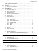
CONTENTS SEAGATE TECHNOLOGY SUPPORT SERVICES . . . . . . . . . . . . . . . . . . . . . . . . . . . . . . . . . . . . . . . . . . . 1 1.0 INTRODUCTION . . . . . . . . . . . . . . . . . . . . . . . . . . . . . . . . . . . . . . . . . . . . . . . . . . . . . . . . . . . . . . . . . . 2 1.1 ABOUT THE SERIAL ATA INTERFACE . . . . . . . . . . . . . . . . . . . . . . . . . . . . . . . . . . . . . . . . . . . . 3 2.0 DRIVE SPECIFICATIONS . . . . . . . . . . . . . . . . . . . . . . . . . . . . . . . . . . . . . .
FIGURES Figure 1. Figure 2. Figure 3. Figure 4. Figure 5. Figure 6. Typical +5V only startup and operation current profile . . . . . . . . . . . . . . . . . . . . . . . . . . . . . . . 9 Serial ATA connectors . . . . . . . . . . . . . . . . . . . . . . . . . . . . . . . . . . . . . . . . . . . . . . . . . . . . . . 17 Attaching SATA cabling . . . . . . . . . . . . . . . . . . . . . . . . . . . . . . . . . . . . . . . . . . . . . . . . . . . . .
Seagate Technology Support Services For information regarding online support and services, visit http://www.seagate.com/www/en-us/about/contact_us/ Available services include: • Presales & Technical support • Global Support Services telephone numbers & business hours • Authorized Service Centers For information regarding Warranty Support, visit http://www.seagate.com/support/warranty-and-returns For information regarding data recovery services, visit http://www.seagate.
1.
1.1 ABOUT THE SERIAL ATA INTERFACE The Serial ATA interface provides several advantages over the traditional (parallel) ATA interface. The primary advantages include: • Easy installation and configuration with true plug-and-play connectivity. It is not normally necessary to set any jumpers or other configuration options. • Thinner and more flexible cabling for improved enclosure airflow and ease of installation. • Scalability to higher performance levels.
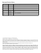
2.0 DRIVE SPECIFICATIONS Unless otherwise noted, all specifications are measured under ambient conditions, at 25°C, and nominal power. For convenience, the phrases the drive and this drive are used throughout this manual to indicate all models. 2.1 SPECIFICATION SUMMARY TABLE The specifications listed in this table are for quick reference.
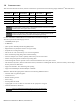
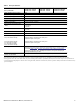
Table 1 Drive specifications Drive specification ST320LT007 - 9ZV142 ST320LT009 - 9WC142 ST320LT014 - 9YK142 Shock, operating (Gs max at 2ms) 350 Shock, nonoperating (Gs max at 2ms) 800 Shock, nonoperating (Gs max at 1ms) 1000 Shock, nonoperating (Gs max at 0.5ms) 600 Vibration, operating (Swept Sine) 1.0 Gs (0 to peak, 5–500 Hz) Vibration, nonoperating 5.
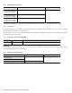
2.2 FORMATTED CAPACITY Formatted capacity* Guaranteed logical blocks (LBA) - 512 emulation Bytes per physical sector ST320LT007 - 9ZV142 ST320LT009 - 9WC142 ST320LT014 - 9YK142 625,142,448 4096 ST250LT007 - 9ZV14C ST250LT009 - 9WC14C ST250LT014 - 9YK14C 488,397,168 ST160LT007 - 9ZV14D ST160LT009 - 9WC14D ST160LT014 - 9YK14D 312,581,808 *One GB equals one billion bytes when referring to hard drive capacity. Accessible capacity may vary depending on operating environment and formatting. 2.2.
2.5 RECORDING AND INTERFACE TECHNOLOGY 4K SECTOR MODELS Interface Serial ATA (SATA) Recording method Perpendicular Recording density BPI (bits/in avg) 1397k Track density TPI (tracks/in avg) 315k Areal density (Gb/in2 avg) 425 Spindle speed (RPM) (± 0.2%) 7200 Maximum Internal transfer rate (Mb/s) 1247 I/O data-transfer rate (Gb/s max) 3.0 Interleave 1:1 Cache buffer 16 MB (16,384 KB) 2.6 PHYSICAL CHARACTERISTICS DRIVE SPECIFICATION Height (mm) (in) 6.8 +/-0.2 0.268 +/-0.
2.8 START/STOP TIMES TIME TO READY TYPICAL MAX @ 25°C Power-on to Ready (sec) 3.5 4.0 Standby to Ready (sec) 3.0 3.0 2.9 POWER SPECIFICATIONS The drive receives DC power (+5V) through a native SATA power connector. 2.9.1 Power consumption Power requirements for the drives are listed in the table on page 8. Typical power measurements are based on an average of drives tested, under nominal conditions, at 25°C ambient temperature.
2.9.1.1 Typical current profile Figure 1. Typical +5V only startup and operation current profile 2.9.2 Deferred spinup Momentus Thin drives do not support the deferred spinup option. If you require this option, refer to the Momentus 5400.3 SATA Blade Server family of drives. 2.9.3 Conducted noise Input noise ripple is measured at the host system power supply across an equivalent 15-ohm resistive load on the +5 volt line.
2.9.5 Power-management modes The drive provides programmable power management to provide greater energy efficiency. In most systems, you can control power management through the system setup program.
2.10 ENVIRONMENTAL SPECIFICATIONS 2.10.1 Ambient temperature Ambient temperature is defined as the temperature of the environment immediately surrounding the drive. Above 1000 feet (305 meters), the maximum temperature is derated linearly by 1°C every 1000 feet. Operating: 0° to 60°C (32° to 140°F) Nonoperating: –40° to 70°C (–40° to 158°F) 2.10.
2.10.5 Shock All shock specifications assume that the drive is mounted securely with the input shock applied at the drive mounting screws. Shock may be applied in the X, Y or Z axis. 2.10.5.1 Operating shock These drives comply with the performance levels specified in this document when subjected to a maximum operating shock of 350 Gs based on half-sine shock pulses of 2ms. Shocks should not be repeated more than two times per second. 2.10.5.
2.11 ACOUSTICS Drive emission of sound is measured consistent with the ECMA-74 and its’ referenced standards. Testing is conducted at room temperature (approximately 25°C). Emission levels are reported as the total A-weighted sound power levels for steady state, idle, and active seek modes of operation. Table 5 Drive A-weighted Sound Power Levels (SWL, BA) IDLE* PERFORMANCE SEEK 2.3 bels (typ) 2.5 bels (max) 2.5 bels (typ) 2.
2.13 RELIABILITY MEASUREMENT TYPE SPECIFICATION Nonrecoverable read errors 1 per 1014 bits read, max Annualized Failure Rate (AFR) <0.
Australian C-Tick (N176) If these models have the C-Tick marking, they comply with the Australia/New Zealand Standard AS/NZ CISPR22 and meet the Electromagnetic Compatibility (EMC) Framework requirements of the Australian Communication Authority (ACA). 2.14.3 FCC verification These drives are intended to be contained solely within a personal computer or similar enclosure (not attached as an external device).
2.15 ENVIRONMENTAL PROTECTION Seagate designs its products to meet environmental protection requirements worldwide, including regulations restricting certain chemical substances. 2.15.1 European Union Restriction of Hazardous Substances (RoHS) The European Union Restriction of Hazardous Substances (RoHS) Directive, restricts the presence of chemical substances, including Lead, Cadmium, Mercury, Hexavalent Chromium, PBB and PBDE, in electronic products, effective July 2006.
3.0 CONFIGURING AND MOUNTING THE DRIVE This section contains the specifications and instructions for configuring and mounting the drive. 3.1 HANDLING AND STATIC-DISCHARGE PRECAUTIONS After unpacking, and before installation, the drive may be exposed to potential handling and electrostatic discharge (ESD) hazards. Observe the following standard handling and static-discharge precautions: CAUTION 3.
3.3 SERIAL ATA CABLES AND CONNECTORS The Serial ATA interface cable consists of four conductors in two differential pairs, plus three ground connections. The cable size may be 30 to 26 AWG with a maximum length of one meter (39.37 inches). See Table 7 for connector pin definitions. Either end of the SATA signal cable can be attached to the drive or host. For direct backplane connection, the drive connectors are inserted directly into the host receptacle.
Measurements shown in Figures 4 and 5 are inches and (mm). Figure 4. Mounting dimensions (for FIPS 140-2 models) — top, side and end view WARNING FIPS 140-2 Models Contain 3 Tamper Evident Stickers with the marking "Tamper Indicator - Do Not Remove". These stickers must remain attached to provide the tamper evidence throughout the life of the drive. Removing these stickers will indicate tampering and void the drive warranty. MOMENTUS THIN PRODUCT MANUAL, GEN-2 REV.
Figure 5. Mounting dimensions (for standard models) — top, side and end view MOMENTUS THIN PRODUCT MANUAL, GEN-2 REV.
4.0 ABOUT FIPS The Federal Information Processing Standard (FIPS) Publication 140-2, FIPS PUB 140-2, is a U.S. government computer security standard used to accredit cryptographic modules. It is titled “Security Requirements for Cryptographic Modules”. The initial publication was on May 25, 2001 and was last updated December 3, 2002.
5.0 SERIAL ATA (SATA) INTERFACE These drives use the industry-standard Serial ATA interface that supports FIS data transfers. It supports ATA programmed input/output (PIO) modes 0–4; multiword DMA modes 0–2, and Ultra DMA modes 0–6. The drive also supports the use of the IORDY signal to provide reliable high-speed data transfers. For detailed information about the Serial ATA interface, refer to the “Serial ATA: High Speed Serialized AT Attachment” specification. 5.
5.3 SUPPORTED ATA COMMANDS The following table lists Serial ATA standard commands that the drive supports. For a detailed description of the ATA commands, refer to the Serial ATA: High Speed Serialized AT Attachment specification. See “S.M.A.R.T. commands” on page 30.for details and subcommands used in the S.M.A.R.T. implementation.
COMMAND NAME COMMAND CODE (IN HEX) S.M.A.R.T. Enable/Disable Autosave B0h/D2h S.M.A.R.T. Enable Operations B0h/D8h S.M.A.R.T. Enable/Disable Auto Offline B0h/DBh S.M.A.R.T. Enable One Attribute Modification B0h/E0h S.M.A.R.T. Execute Offline B0h/D4h S.M.A.R.T. Read Attribute Thresholds B0h/D1h S.M.A.R.T. Read Data B0h/D0h S.M.A.R.T. Read Log Sector B0h/D5h S.M.A.R.T. Return Status B0h/DAh S.M.A.R.T. Save Attribute Values B0h/D3h S.M.A.R.T. Write Attribute Thresholds B0h/D7h S.M.A.R.
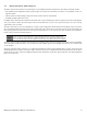
5.3.1 Identify Device command The Identify Device command (command code ECH) transfers information about the drive to the host following power up. The data is organized as a single 512-byte block of data, whose contents are shown in the table on page 27. All reserved bits or words should be set to zero. Parameters listed with an “x” are drive-specific or vary with the state of the drive. The following commands contain drive-specific features that may not be included in the Serial ATA specification.
WORD DESCRIPTION VALUE 60–61 Total number of user-addressable sectors This field contains a value that is one greater than the total number of user-addressable sectors. The maximum value that shall be placed in this field is 0FFFFFFFh. The 0FFFFFFFh value applies to all capacities over 137GB (see Section 2.2 and 2.3 for related information).
WORD DESCRIPTION VALUE 100– 103 Total number of user-addressable LBA sectors available (see Section 2.2 for related information) These words are required for drives that support the 48-bit addressing feature. Maximum value: 0000FFFFFFFFFFFFh.
BIT WORD 88 0 Ultra DMA mode 0 is supported. 1 Ultra DMA mode 1 is supported. 2 Ultra DMA mode 2 is supported. 3 Ultra DMA mode 3 is supported. 4 Ultra DMA mode 4 is supported. 5 Ultra DMA mode 5 is supported 6 Ultra DMA mode 6 is supported 8 Ultra DMA mode 0 is currently active. 9 Ultra DMA mode 1 is currently active. 10 Ultra DMA mode 2 is currently active. 11 Ultra DMA mode 3 is currently active. 12 Ultra DMA mode 4 is currently active. 13 Ultra DMA mode 5 is currently active.
5.3.2 Set Features command This command controls the implementation of various features that the drive supports. When the drive receives this command, it sets BSY, checks the contents of the Features register, clears BSY and generates an interrupt. If the value in the register does not represent a feature that the drive supports, the command is aborted. Power-on default has the read look-ahead and write caching features enabled.
5.3.3 S.M.A.R.T. commands S.M.A.R.T. provides near-term failure prediction for disk drives. When S.M.A.R.T. is enabled, the drive monitors predetermined drive attributes that are susceptible to degradation over time. If self-monitoring determines that a failure is likely, S.M.A.R.T. makes a status report available to the host. Not all failures are predictable. S.M.A.R.T. predictability is limited to the attributes the drive can monitor. For more information on S.M.A.R.T.
Index A ACA 15 acoustics 5, 13 Active mode 10 Address 23 AFR 14 Agency certification 14 Altitude 11 Altitude, nonoperating 4 Altitude, operating 4 Ambient temperature 4, 11 ambient temperature 7 Annualized Failure Rate 14 Annualized Failure Rate (AFR) 5 Areal density 4, 7 ATA commands 23 ATA data-transfer modes supported 4 Australia/New Zealand Standard AS/NZ CISPR22 15 Australian Communication Authority (ACA) 15 Australian C-Tick 15 Average seek time 7 Average seek, read 4 B bels 5 BPI 4 buffer 4, 7 Bytes
Guaranteed lba 4, 6 guaranteed sectors 6 H handling 17 Handling precautions 17 heads 6 Height 4 height 7 Humidity 11 humidity 4 I I/O data-transfer rate 4, 7 Identify 23 Identify Device 23 Identify Device command 25 Idle 8, 24 Idle and Standby timers 10 Idle Immediate 24 Idle mode 4, 10 Idle mode power 8 Information Technology Equipment (ITE) 14 Initialize Device Parameters 23 Input noise ripple 9 Interface 7 interface 22 Interleave 7 Internal data transfer rate 4 Internal data-transfer rate 7 ITE 14 N N
Read Verify Sectors Extended 23 Read Verify Sectors without Retries 23 Read/write heads 6 Read/write power 4 read/write power and current 8 Recording density 4, 7 Recording method 7 Recording technology 7 Relative humidity 4, 11 Reliability 14 resistance 9 Retries 23 RF 13 RoHS 16 RPM 4 RRL 14 S S.M.A.R.T. 24 S.M.A.R.T.
Seagate Technology LLC AMERICAS Seagate Technology LLC 10200 South De Anza Boulevard, Cupertino, California 95014, United States, 408-658-1000 ASIA/PACIFIC Seagate Singapore International Headquarters Pte. Ltd. 7000 Ang Mo Kio Avenue 5, Singapore 569877, 65-6485-3888 EUROPE, MIDDLE EAST AND AFRICA Seagate Technology SAS 16-18 rue du Dôme, 92100 Boulogne-Billancourt, France, 33 1-4186 10 00 Publication Number: 100625253, Rev.