Product Manual Momentus Thin Series SATA ® ST92503010AS ST91603010AS 100586949 Rev.
Revision history Revision Rev. A Rev. B Date 10/21/09 03/02/10 Sheets affected or comments Initial release. 3-4, 10 & 35. Copyright © 2010 Seagate Technology LLC. All rights reserved. Printed in U.S.A. Publication number: 100586949, Rev. B March 2010 Seagate, Seagate Technology and the Wave logo are registered trademarks of Seagate Technology LLC in the United States and/or other countries.
Contents 1.0 Introduction. . . . . . . . . . . . . . . . . . . . . . . . . . . . . . . . . . . . . . . . . . . . . . . . . . . . . . . . . . . . . . . . . . . 1 1.1 About the Serial ATA interface . . . . . . . . . . . . . . . . . . . . . . . . . . . . . . . . . . . . . . . . . . . . . . 2 2.0 Drive specifications . . . . . . . . . . . . . . . . . . . . . . . . . . . . . . . . . . . . . . . . . . . . . . . . . . . . . . . . . . . . 3 2.1 Specification summary table . . . . . . . . . . . . . . . . . . . .
ii Momentus Thin Series SATA Product Manual, Rev.
List of Figures Figure 1. Figure 2. Figure 3. Figure 4. Typical +5V only startup and operation current profile . . . . . . . . . . . . . . . . . . . . . . . . . . . . . . . 8 Serial ATA connectors . . . . . . . . . . . . . . . . . . . . . . . . . . . . . . . . . . . . . . . . . . . . . . . . . . . . . . 17 Attaching SATA cabling . . . . . . . . . . . . . . . . . . . . . . . . . . . . . . . . . . . . . . . . . . . . . . . . . . . . . 17 Mounting dimensions—top, side and end view . . . . . . . . . . . . . .
1.0 Introduction This manual describes the functional, mechanical and interface specifications for the following Seagate Momentus® Thin Series SATA model drives: • ST92503010AS • ST91603010AS These drives provide the following key features: • 5400-RPM spindle speed. • 8-MB buffer. • Quiet operation. Fluid Dynamic Bearing (FDB) motor. • High instantaneous (burst) data-transfer rates (up to 3Gb/s). • Perpendicular recording technology. • State-of-the-art cache and on-the-fly error-correction algorithms.
1.1 About the Serial ATA interface The Serial ATA interface provides several advantages over the traditional (parallel) ATA interface. The primary advantages include: • Easy installation and configuration with true plug-and-play connectivity. It is not normally necessary to set any jumpers or other configuration options. • Thinner and more flexible cabling for improved enclosure airflow and ease of installation. • Scalability to higher performance levels.
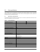
2.0 Drive specifications Unless otherwise noted, all specifications are measured under ambient conditions, at 25°C, and nominal power. For convenience, the phrases the drive and this drive are used throughout this manual to indicate the ST92503010AS and ST91603010AS models. 2.1 Specification summary table The specifications listed in this table are for quick reference. For details on specification measurement or definition, see the appropriate section of this manual.
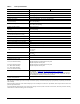
Table 1: Drive specifications Drive specification ST92503010AS ST91603010AS Idle mode, low power (typical) 0.58W Standby mode 0.20W (typical)*** Sleep mode 0.
2.2 Formatted capacity Model Formatted capacity* Guaranteed sectors ST92503010AS 250 GB 488,397,168 ST91603010AS 160 GB 312,581,808 Bytes per sector 512 *One GB equals one billion bytes when referring to hard drive capacity. Accessible capacity may vary depending on operating environment and formatting. 2.2.1 LBA mode When addressing these drives in LBA mode, all blocks (sectors) are consecutively numbered from 0 to n–1, where n is the number of guaranteed sectors as defined above.
2.6 Physical characteristics Drive specification Height (mm) (in) 6.8 +/-0.2 0.268 +/-0.0079 Width (mm) (in) 69.85 +/-0.25 2.75 +/-0.0098 Length (mm) (in) 100.35 +0.20/-0.25 3.951 +0.008/-0.010 Weight (max) ST92503010AS and ST91603010AS 2.7 92.0 g 0.203 lb Seek time Seek measurements are taken with nominal power at 25°C ambient temperature. All times are measured using drive diagnostics.
2.9 Power specifications The drive receives DC power (+5V) through a native SATA power connector. 2.9.1 Power consumption Power requirements for the drives are listed in the table on page 7. Typical power measurements are based on an average of drives tested, under nominal conditions, at 25°C ambient temperature. • Spinup power Spinup power is measured from the time of power-on to the time that the drive spindle reaches operating speed.
2.9.1.1 Typical current profile Figure 1. Typical +5V only startup and operation current profile 2.9.2 Deferred spinup Momentus Thin Series SATA drives do not support the deferred spinup option. If you require this option, refer to the Momentus 5400.3 SATA Blade Server family of drives. 2.9.3 Conducted noise Input noise ripple is measured at the host system power supply across an equivalent 15-ohm resistive load on the +5 volt line.
2.9.5 Power-management modes The drive provides programmable power management to provide greater energy efficiency. In most systems, you can control power management through the system setup program.
2.10 Environmental specifications 2.10.1 Ambient temperature Ambient temperature is defined as the temperature of the environment immediately surrounding the drive. Above 1000 feet (305 meters), the maximum temperature is derated linearly by 1°C every 1000 feet. Operating: 0° to 60°C (32° to 140°F) Nonoperating: –40° to 70°C (–40° to 158°F) 2.10.
2.10.5 Shock All shock specifications assume that the drive is mounted securely with the input shock applied at the drive mounting screws. Shock may be applied in the X, Y or Z axis. 2.10.5.1 Operating shock These drives comply with the performance levels specified in this document when subjected to a maximum operating shock of 350 Gs based on half-sine shock pulses of 2ms. Shocks should not be repeated more than two times per second. 2.10.5.
2.11 Acoustics Drive emission of sound is measured consistent with the ECMA-74 and its’ referenced standards. Testing is conducted at room temperature (approximately 25°C). Emission levels are reported as the total A-weighted sound power levels for steady state, idle, and active seek modes of operation. Table 5: Drive A-weighted Sound Power Levels (SWL, BA) Idle* Performance seek 2.0 bels (typ) 2.2 bels (max) 2.4 bels (typ) 2.
2.13 Reliability Measurement type Specification Nonrecoverable read errors 1 per 1014 bits read, max. Annualized Failure Rate (AFR) <0.
Australian C-Tick (N176) If these models have the C-Tick marking, they comply with the Australia/New Zealand Standard AS/NZ CISPR22 and meet the Electromagnetic Compatibility (EMC) Framework requirements of the Australian Communication Authority (ACA). 2.14.3 FCC verification These drives are intended to be contained solely within a personal computer or similar enclosure (not attached as an external device).
2.15 Environmental protection Seagate designs its products to meet environmental protection requirements worldwide, including regulations restricting certain chemical substances. 2.15.1 European Union Restriction of Hazardous Substances (RoHS) The European Union Restriction of Hazardous Substances (RoHS) Directive, restricts the presence of chemical substances, including Lead, Cadmium, Mercury, Hexavalent Chromium, PBB and PBDE, in electronic products, effective July 2006.
3.0 Configuring and mounting the drive This section contains the specifications and instructions for configuring and mounting the drive. 3.1 Handling and static-discharge precautions After unpacking, and before installation, the drive may be exposed to potential handling and electrostatic discharge (ESD) hazards.
3.2 Configuring the drive Each drive on the Serial ATA interface connects in a point-to-point configuration with the Serial ATA host adapter. There is no master/slave relationship because each drive is considered a master in a point-to-point relationships. If two drives are attached on one Serial ATA host adapter, the host operating system views the two devices as if they were both “masters” on two separate ports. This means both drives behave as if they are Device 0 (master) devices.
3.4 Drive mounting You can mount the drive using four screws in the side-mounting holes or four screws in the bottom-mounting holes. See Figure 4 for drive mounting dimensions. Follow these important mounting precautions when mounting the drive: • Allow a minimum clearance of 0.030 inches (0.76 mm) around the entire perimeter of the drive for cooling. • Use only M3 UNC mounting screws. • Do not overtighten the mounting screws. Maximum torque: 4.0 in-lb (0.4519 N-m). • Four (4) threads (0.080 inches, 2.
4.0 Serial ATA (SATA) interface These drives use the industry-standard Serial ATA interface that supports FIS data transfers. It supports ATA programmed input/output (PIO) modes 0–4; multiword DMA modes 0–2, and Ultra DMA modes 0–6. The drive also supports the use of the IORDY signal to provide reliable high-speed data transfers. For detailed information about the Serial ATA interface, refer to the “Serial ATA: High Speed Serialized AT Attachment” specification. 4.
Table 7: Segment Power Serial ATA connector pin definitions Pin Function Definition P1 V33 3.3V power P2 V33 3.3V power P3 V33 3.
4.3 Supported ATA commands The following table lists Serial ATA standard commands that the drive supports. For a detailed description of the ATA commands, refer to the Serial ATA: High Speed Serialized AT Attachment specification. See “S.M.A.R.T. commands” on page 29.for details and subcommands used in the S.M.A.R.T. implementation.
Command name Command code (in hex) Note: Individual Set Max commands are identified by the value placed in the Set Max Features register as defined to the right. Address: Password: Lock: Unlock: Freeze Lock: Set Multiple Mode C6h S.M.A.R.T. Disable Operations B0h/D9h S.M.A.R.T. Enable/Disable Autosave B0h/D2h S.M.A.R.T. Enable Operations B0h/D8h S.M.A.R.T. Enable/Disable Auto Offline B0h/DBh S.M.A.R.T. Enable One Attribute Modification B0h/E0h S.M.A.R.T. Execute Offline B0h/D4h S.M.A.R.T.
Command name Command code (in hex) Standby Immediate E0h ATA-standard security commands Security Set Password F1h Security Unlock F2h Security Erase Prepare F3h Security Erase Unit F4h Security Freeze Lock F5h Security Disable Password F6h Momentus Thin Series SATA Product Manual, Rev.
4.3.1 Identify Device command The Identify Device command (command code ECH) transfers information about the drive to the host following power up. The data is organized as a single 512-byte block of data, whose contents are shown in the table on page 27. All reserved bits or words should be set to zero. Parameters listed with an “x” are drive-specific or vary with the state of the drive. The following commands contain drive-specific features that may not be included in the Serial ATA specification.
Word Description Value 59 Number of sectors transferred during a Read Multiple or Write Multiple command xxxxH 60–61 Total number of user-addressable sectors This field contains a value that is one greater than the total number of user-addressable sectors. The maximum value that shall be placed in this field is 0FFFFFFFh. The 0FFFFFFFh value applies to all capacities over 137GB (see Section 2.2 and 2.3 for related information).
Word Description Value 95–99 ATA-reserved 0000H 100– 103 Total number of user-addressable LBA sectors available (see Section 2.2 for related information) These words are required for drives that support the 48-bit addressing feature. Maximum value: 0000FFFFFFFFFFFFh.
Bit Word 88 0 Ultra DMA mode 0 is supported. 1 Ultra DMA mode 1 is supported. 2 Ultra DMA mode 2 is supported. 3 Ultra DMA mode 3 is supported. 4 Ultra DMA mode 4 is supported. 5 Ultra DMA mode 5 is supported 6 Ultra DMA mode 6 is supported 8 Ultra DMA mode 0 is currently active. 9 Ultra DMA mode 1 is currently active. 10 Ultra DMA mode 2 is currently active. 11 Ultra DMA mode 3 is currently active. 12 Ultra DMA mode 4 is currently active. 13 Ultra DMA mode 5 is currently active.
4.3.2 Set Features command This command controls the implementation of various features that the drive supports. When the drive receives this command, it sets BSY, checks the contents of the Features register, clears BSY and generates an interrupt. If the value in the register does not represent a feature that the drive supports, the command is aborted. Power-on default has the read look-ahead and write caching features enabled.
4.3.3 S.M.A.R.T. commands S.M.A.R.T. provides near-term failure prediction for disk drives. When S.M.A.R.T. is enabled, the drive monitors predetermined drive attributes that are susceptible to degradation over time. If self-monitoring determines that a failure is likely, S.M.A.R.T. makes a status report available to the host. Not all failures are predictable. S.M.A.R.T. predictability is limited to the attributes the drive can monitor. For more information on S.M.A.R.T.
5.0 Seagate Technology support services Internet For information regarding Seagate products and services, visit www.seagate.com. Worldwide support is available 24 hours daily by email for your questions. Presales Support: Presales@Seagate.com Technical Support: DiscSupport@Seagate.com Warranty Support: http://www.seagate.com/www/en-us/support/warranty_&_returns_assistance direct.seagate.com direct.seagate.com is the industry's first Web portal designed specifically for OEMs and distributors.
Customer Service Operations Presales Support Our Presales Support staff can help you determine which Seagate products are best suited for your specific application or computer system, as well as product availability and compatibility. Technical Support Seagate technical support is available to assist you online at support.seagate.com or through one of our call centers. Have your system configuration information and your "ST" model/product number available.
32 Momentus Thin Series SATA Product Manual, Rev.
Index A ACA 14 acoustics 4, 12 Active mode 9 Address 21 AFR 13 Agency certification 13 Altitude 10 Altitude, nonoperating 4 Altitude, operating 4 Ambient temperature 4, 10 ambient temperature 6 Annualized Failure Rate 13 Annualized Failure Rate (AFR) 4 Areal density 3, 5 ATA commands 21 ATA data-transfer modes supported 3 Australia/New Zealand Standard AS/NZ CISPR22 14 Australian Communication Authority (ACA) 14 Australian C-Tick 14 Average seek time 6 Average seek, read 3 B bels 4 BPI 3 buffer 3, 5 Bytes
Guaranteed sectors 3, 5 guaranteed sectors 5 H handling 16 Handling precautions 16 heads 5 Height 3 height 6 Humidity 10 humidity 4 I I/O data-transfer rate 3, 5 Identify 21 Identify Device 21 Identify Device command 24 Idle 7, 22 Idle and Standby timers 9 Idle Immediate 22 Idle mode 4, 9 Idle mode power 7 Information Technology Equipment (ITE) 13 Initialize Device Parameters 21 Input noise ripple 8 Interface 5 interface 19 Interleave 5 Internal data transfer rate 3 Internal data-transfer rate 5 ITE 13 N
Read/write heads 5 Read/write power 3 read/write power and current 7 Recording density 3, 5 Recording method 5 Recording technology 5 Relative humidity 4, 10 Reliability 13 resistance 8 Retries 21 RF 12 RoHS 15 RPM 3 RRL 13 S S.M.A.R.T. 22 S.M.A.R.T.
36 Momentus Thin Series SATA Product Manual, Rev.
Seagate Technology LLC 920 Disc Drive, Scotts Valley, California 95066-4544, USA Publication Number: 100586949, Rev.