
Product manual


University of Hertfordshire
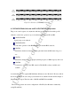
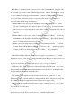
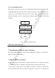
Figure 6.3 PACR Configuration for Mode 0, Submode 00
6.4 IDE I/O Register Descriptions
Communication to or from the drive is through an I/O Register that routes the input or
output data to or from registers (selected) by a code on signals from the host (CS1FX-,
CS3FX-, DA2, DA1, DA0, DIOR- and DIOW-). Thus the project followed the same routine.
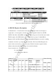
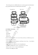
The I/O register of the IDE interface can be divided in two groups: Command Block
Registers and Control Block Registers.The Command Block Registers are used for sending
commands to the drive or posting status from the drive. The Control Block Registers are
used for drive control and to post alternate status. Table 6.2 lists these registers and the
addresses that select them. The figure also shows the Port B value.
Logic conventions are: A = signal asserted
N = signal negated
x = does not matter which it is
Addresses Functions Value of Port B
CS1FX- CS3FX- DA2 DA1 DA0
READ
(DIOR-)
WRITE
(DIOW-)
Control Block Registers
Read Write
N N X X X
Data bus high
impe.
Not used
XXh XXh
N A 0 X X
Data bus high Not used
XXh XXh