Series 700 Workstation to B–Class Workstation Upgrade Procedures Part No. A4190–90013 Edition E1096 Hewlett–Packard Company 3404 East Harmony Rd.
Hewlett-Packard Co. 1996 First Printing: October 1996 UNIX is a registered trademark in the United States and other countries, licensed exclusively through X/Open Company Limited NOTICE The information contained in this document is subject to change without notice. HEWLETT–PACKARD MAKES NO WARRANTY OF ANY KIND WITH REGARD TO THIS MATERIAL INCLUDING BUT NOT LIMITED TO THE IMPLIED WARRANTIES OF MERCHANTABILITY AND FITNESS FOR A PARTICULAR PURPOSE.
Emissions Regulations Federal Communications Commission (FCC) The Federal Communications Commission of the U.S. government regulates the radio frequency energy emanated by computing devices through published regulations. These regulations specify the limits of radio frequency emission to protect radio and television reception. All HP nodes and peripherals have been tested and comply with these limits. The FCC regulations also require that computing devices used in the U.S.
Warnings and Cautions WARNING: Removing device cover may expose sharp edges in equipment chassis. To avoid injury, use care when installing customer add– on devices WARNUNG: Das Entfernen der Geräteabdeckung legt die scharfen Kanten im Inneren des Gerätes frei.
700 Series Workstation to B–Class Workstation Trade–Up Installation Instructions. These instructions document the installation of a B–Class workstation when trading up from your 700 Series workstation. The procedures you perform may vary depending on the configuration of your Series 700 workstation. The installation procedures are divided into the following areas: D Removing components from your Series 700 workstation that can be used in the B–Class workstation.
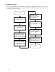
Upgrade Overview An overview of the 700 Series to B–Class Workstation Trade–up Installation procedures are shown in the following flowchart. Depending on your upgrade hardware and software configuration you may not have to complete all of these procedures. Start Follow the installation procedures in the B–Class Owners Guide (A4190–90014) Shutdown your Series 700 workstation Power up your B–Class workstation Power down your Series 700 workstation Install HP–UX 10.
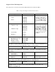
Supported Series 700 Components The components you can use from the Series 700 workstation are described in Table 1 Table 1 Components Supported in the B–Class System Component Product/Part Number Comments Monitors 17 inch A4330A/B A4032A/B 20 inch A4331A/B A2094A/B A4033A/B The EVC to DB adapter cable ((HP ppart# 8120–6861)) i to t connectt the th monitor it to t is the B–Class built–in graphics. Storage Devices 1 GB SE 1in. high 9164–0395 0950–2601 0950–3037 2 GB SE 1in.
Powering Down Your Series 700 Workstation Before you power down your Series 700 workstation, check the type of graphics cards in your system by typing: graphinfo You will need this information when you are performing this upgrade. CAUTION: Although the chances of corrupting your system are very small, you must back up your system, before you shut your system down, to perform this upgrade.
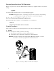
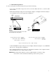
2. Internal Storage Devices To remove and replace the internal storage devices perform the following: A. To remove an internal storage devices from your Series 700 system refer to your Series 700 Owners Guide. B. The hard disk jumper settings are shown in Figure 2, Figure 3, and Figure 4. Ensure the jumpers on your disk drive are set to the appropriate configuration.
LED SCSI ID Second Drive 1 2 34 56 5 NOTICE: A0, A1 and A3 are the SCSI ID jumpers. The jumpers TE, SS, WS and I/O should be removed. The jumper EP and INT should be in place NOTICE: The first three jumpers (1, 2, and 3) should be removed. The SCSI ID jumpers are jumpers 4, 5, and 6. SCSI ID 5 Seagate Disk Drive Models – ST32430N ST31230N ST31200N HP Part Numbers – 0950–2601 0950–2606 Quantum Disk Drive Model – LPS1080S HP Part Number – 9164–0395 Figure 3.
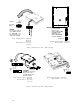
SCSI-2 Terminators (must be removed) Jumpers Target ID Default Jumpers NOTICE: SCSI ID 6 is the default for root and is NOT recommended for CD-ROM drive 2 CD ROM Drive HP Part Number A4325–60001 or A3416–60001 Figure 5. CD–ROM Jumper Settings Figure 6.
3. EISA Cards To remove and replace any of EISA cards, perform the following: A. To remove an EISA card from your Series 700 system refer to your Series 700 Owners Guide. B. To install an EISA card in your B–Class workstation see Figure 7, and refer to the Model B132L/B160L Owner’s Guide (A4190–90014). NOTICE:The X.25 link and the 10/100VG LAN Link require HP–UX 10.20 drivers to be installed. 4. Graphics Cards To remove and replace any of the graphic cards, perform the following: A.
5. Install the B–Class Workstation Install the B–Class workstation according the Hardware Installation Card, B–Class (HP part# A4190–90010) 6. Install HP–UX 10.20 Device Drivers To install the device drivers on the B–Class workstation, perform the following: A. Power up the B–Class workstation B. To install the HP–UX 10.20 Device Drivers the instructions and the Release Notes that accompany the drivers. 7.
Part Number: A4190–90013 Printed in U.S.A.