
Specifications

12/01 Application ModuleX Service 59
Honeywell
5. Hard Disk Drive Tray
5.1 Drive Tray Description
Overview
The Hard Disk Drive Tray (HDDT) contains the coprocessor hard disk
drive(s). A maximum of two drives can exist in this tray.
The primary (first) drive is always mounted on the right side. This is
done for cooling reasons and must be adhered to in all cases. This drive
will always have device address 6 (physical pinning).
An optional second drive is mounted on the left side. This drive will
always have device address 5 (physical pinning).
A printed circuit board in the tray is used to provide a means of
connecting the SCSI bus to each drive as well as routing it through the
backplane to the HDDT I/O board. DC power from the backplane is also
routed through this board to the disk drives.
Disk drives are separately replaceable in the event of failure. The drive
tray (including internal circuit board) is only replaceable as a single unit.
When ordering a replacement drive tray, it will be supplied without
drives. Disk drives are ordered separately.
The spare parts section of this manual supports this replacement strategy.
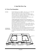
Hard disk drive
tray (front view)
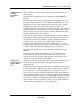
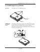
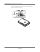
The following illustration shows the hard disk drive tray as you would
see it after removing it from the node chassis. Notice the placement of
the disk drives. The primary drive is always mounted on the right side of
the tray.
51172
Optional 2nd Drive
(Address 5)
Tray Cover
SCSI Interface Cable
(From Coprocessor)
Primary Drive
(Address 6)
Slot to View
Drive Indicators