Product Manual NL35 Series FC ST3500071FC ST3400071FC 100343673 Rev.
©2007, Seagate Technology LLC All rights reserved. Publication number: 100343673, Rev. D August 2007 Seagate, Seagate Technology and the Wave logo are registered trademarks of Seagate Technology LLC in the United States and/or other countries. NL35 Series, SeaTools and SeaTDD are either trademarks or registered trademarks of Seagate Technology LLC or one of its affiliated companies in the United States and/or other countries.
Contents 1.0 Scope . . . . . . . . . . . . . . . . . . . . . . . . . . . . . . . . . . . . . . . . . . . . . . . . . . . . . . . . . . . . . . . . . . . . . . . . 1 2.0 Applicable standards and reference documentation . . . . . . . . . . . . . . . . . . . . . . . . . . . . . . . . . 2.1 Standards . . . . . . . . . . . . . . . . . . . . . . . . . . . . . . . . . . . . . . . . . . . . . . . . . . . . . . . . . . . . . . 2.1.1 Electromagnetic compatibility. . . . . . . . . . . . . . . . . . . . . . . . . .
6.4 Environmental limits . . . . . . . . . . . . . . . . . . . . . . . . . . . . . . . . . . . . . . . . . . . . . . . . . . . . . . 6.4.1 Temperature . . . . . . . . . . . . . . . . . . . . . . . . . . . . . . . . . . . . . . . . . . . . . . . . . . . . 6.4.2 Relative humidity . . . . . . . . . . . . . . . . . . . . . . . . . . . . . . . . . . . . . . . . . . . . . . . . 6.4.3 Effective altitude (sea level) . . . . . . . . . . . . . . . . . . . . . . . . . . . . . . . . . . . . . . . . 6.4.
9.6.1 9.6.2 9.6.3 9.6.4 10.0 TTL input characteristics . . . . . . . . . . . . . . . . . . . . . . . . . . . . . . . . . . . . . . . . . . LED driver signals . . . . . . . . . . . . . . . . . . . . . . . . . . . . . . . . . . . . . . . . . . . . . . . Differential PECL output. . . . . . . . . . . . . . . . . . . . . . . . . . . . . . . . . . . . . . . . . . . Differential PECL input. . . . . . . . . . . . . . . . . . . . . . . . . . . . . . . . . . . . . . . . . . . .
vi NL35 Series FC Product Manual, Rev.
List of Figures Figure 1. Figure 2. Figure 3. Figure 4. Figure 5. Figure 6. Figure 7. Figure 8. Figure 9. Figure 10. Figure 11. Figure 12. Figure 13. NL35 Series family disc drive . . . . . . . . . . . . . . . . . . . . . . . . . . . . . . . . . . . . . . . . . . . . . . . . . 1 DC current and power vs. input/output operations per second (1 Gbit). . . . . . . . . . . . . . . . . 27 DC current and power vs. input/output operations per second (2 Gbit). . . . . . . . . . . . . . . . .
viii NL35 Series FC Product Manual, Rev.
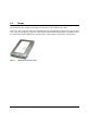
1.0 Scope This manual describes Seagate Technology® LLC, NL35 Series (Fibre Channel) disc drives. NL35 Series drives support the Fibre Channel Arbitrated Loop and SCSI Fibre Channel Protocol specifications to the extent described in this manual. The Fibre Channel Interface Manual (part number 77767496) describes the general Fibre Channel Arbitrated Loop characteristics of this and other Seagate Fibre Channel drives. Figure 1. NL35 Series family disc drive NL35 Series FC Product Manual, Rev.
2 NL35 Series FC Product Manual, Rev.
2.0 Applicable standards and reference documentation The drive has been developed as a system peripheral to the highest standards of design and construction. The drive depends upon its host equipment to provide adequate power and environment in order to achieve optimum performance and compliance with applicable industry and governmental regulations. Special attention must be given in the areas of safety, power distribution, shielding, audible noise control, and temperature regulation.
2.2 Electromagnetic compliance Seagate uses an independent laboratory to confirm compliance with the directives/standards for CE Marking and C-Tick Marking. The drive was tested in a representative system for typical applications. The selected system represents the most popular characteristics for test platforms. The system configurations include: • Typical current use microprocessor • 3.
2.4 Reference documents NL35 Series FC Installation Guide Seagate part number: 100343674 Fibre Channel Interface Manual Seagate part number: 77767496 ANSI Fibre Channel Documents X3.230-1994 X3.297.1997 X3.303.1998 X3.272-1996 X3.
6 NL35 Series FC Product Manual, Rev.
3.0 General description NL35 Series drives combine Tunneling Magnetoresistive (TMR) heads and a Fibre Channel interface to provide high performance, high capacity data storage for a variety of systems including engineering workstations, network servers, mainframes, and supercomputers.
3.
3.2 Media description The media used on the drive has an aluminum substrate coated with a thin film magnetic material, overcoated with a proprietary protective layer for improved durability and environmental protection. 3.3 Performance • Programmable multi-segmentable cache buffer • 200 Mbytes/sec maximum instantaneous data transfers per port • 7K RPM spindle; average latency = 4.17 msec • Command queuing of up to 64 commands • Background processing of queue • Supports start and stop commands 3.
3.5.1 Programmable drive capacity Using the Mode Select command, the drive can change its capacity to something less than maximum. See the Mode Select Parameter List table in the FC Interface Product Manual. Refer to the Parameter list block descriptor number of blocks field. A value of zero in the number of blocks field indicates that the drive shall not change the capacity it is currently formatted to have.
4.0 Performance characteristics This section provides detailed information concerning performance-related characteristics and features of NL35 Series drives. 4.1 Internal drive characteristics Drive capacity* Read/write data heads Bytes per track Bytes per surface Tracks per surface (total) Tracks per inch Peak bits per inch Internal data rate Disc rotation speed Avg rotational latency ST3500071FC ST3400071FC 500.0 ........................ 400.0........................ ..................
4.2.
4.3 Start/stop time If the Motor Start option is disabled, the drive becomes ready within 25 seconds after DC power is applied. If a recoverable error condition is detected during the start sequence, the drive executes a recovery procedure and the time to become ready may exceed 25 seconds. Stop time is less than 30 seconds (maximum) from removal of DC power.
Case B—A Read command requests data, and the first logical block is not in any segment of the cache: 1. The drive fetches the requested logical blocks from the disc and transfers them into a segment, and then from there to the host in accordance with the Mode Select Disconnect/Reconnect parameters, page 02h. 2. If the prefetch feature is enabled, refer to section 4.5.2 for operation from this point.
To enable Prefetch, use Mode Select page 08h, byte 12, bit 5 (Disable Read Ahead—DRA bit). DRA bit = 0 enables prefetch. Since data that is prefetched replaces data already in some buffer segments, the host can limit the amount of prefetch data to optimize system performance. The Max Prefetch field (bytes 8 and 9) limits the amount of prefetch. The drive does not use the Prefetch Ceiling field (bytes 10 and 11).
16 NL35 Series FC Product Manual, Rev.
5.
5.1.1 Recoverable Errors Recovereable errors are those detected and corrected by the drive, and do not require user intervention. Recoverable Data errors will use correction, although ECC on-the-fly is not considered for purposes of recovered error specifications. Recovered Data error rate is determined using read bits transferred for recoverable errors occurring during a read, and using write bits transferred for recoverable errors occurring during a write. 5.1.
5.2.1 Mean Time Between Failure (MTBF) The production disc drive shall achieve an MTBF of 1,000,000 hours when operated in an environment that ensures the HDA case temperatures specified in Section 6.4 are not exceeded. Short-term excursions up to the specification limits of the operating environment will not affect MTBF performance. Continual or sustained operation at case temperatures above the values shown in Section 6.4.1 may degrade product reliability.
5.2.4 S.M.A.R.T. S.M.A.R.T. is an acronym for Self-Monitoring Analysis and Reporting Technology. This technology is intended to recognize conditions that indicate imminent drive failure and is designed to provide sufficient warning of a failure to allow you to back up the data before an actual failure occurs. Note. The drive’s firmware monitors specific attributes for degradation over time but can’t predict instantaneous drive failures.
Error rate is the number of errors per operation. The algorithm that S.M.A.R.T. uses to record rates of error is to set thresholds for the number of errors and their interval. If the number of errors exceeds the threshold before the interval expires, the error rate is considered to be unacceptable. If the number of errors does not exceed the threshold before the interval expires, the error rate is considered to be acceptable.
5.2.6 Drive Self Test (DST) Drive Self Test (DST) is a technology designed to recognize drive fault conditions that qualify the drive as a failed unit. DST validates the functionality of the drive at a system level. There are two test coverage options implemented in DST: 1. Extended test 2. Short text The most thorough option is the extended test that performs various tests on the drive and scans every logical block address (LBA) of the drive.
5.2.6.2.2 Invoking DST To invoke DST, submit the Send Diagnostic command with the appropriate Function Code (001b for the short test or 010b for the extended test) in bytes 1, bits 5, 6, and 7. Refer to the Fibre Channel Interface Product Manual, part number 77767496, for additional information about invoking DST. 5.2.6.2.3 Short and extended tests DST has two testing options: 1. short 2. extended These testing options are described in the following two subsections.
5.2.6.2.5 Abort There are several ways to abort a diagnostic. You can use a SCSI Bus Reset or a Bus Device Reset message to abort the diagnostic. You can abort a DST executing in background mode by using the abort code in the DST Function Code field. This will cause a 01 (self-test aborted by the application client) code to appear in the self-test results values log. All other abort mechanisms will be reported as a 02 (self-test routine was interrupted by a reset condition). 5.2.
6.0 Physical/electrical specifications This section provides information relating to the physical and electrical characteristics of the drive. 6.1 AC power requirements None. 6.2 DC power requirements The voltage and current requirements for a single drive are shown below. Values indicated apply at the drive connector. Table 11: ST3500071FC/ST3400071FC DC power requirements 1 Gbit Notes (Amps) (Amps) (Amps) (Amps) +5V +12V [2] +5V +12V [2] [5] ±5% ±5% [2] ±5% ±5% [2] [1] [7] 0.94 0.
[5] [6] [7] See paragraph 6.2.1, "Conducted noise immunity." Specified voltage tolerance includes ripple, noise, and transient response. Operating condition is defined as random 8 block reads at 161 I/Os per second. Current and power specified at nominal voltages. Decreasing +5 volt supply by 5% increases 5 volt current by <0.5%. Decreasing +12 volt supply by 5% increases 12 volt current by 1.4%.
6.3 Power dissipation Typical power dissipation under idle conditions is 10.49 watts (35.79 BTUs per hour) during 1 Gbit operation. Typical power dissipation under idle conditions is 10.75 watts (36.68 BTUs per hour) during 2 Gbit operation. To obtain operating power for typical random read operations, refer to the following I/O rate curve (see Figure 2).
6.4 Environmental limits Temperature and humidity values experienced by the drive must be such that condensation does not occur on any drive part. Altitude and atmospheric pressure specifications are referenced to a standard day at 58.7°F (14.8°C). Maximum wet bulb temperature is 82°F (28°C). 6.4.1 Temperature a. Operating The maximum allowable continuous or sustained HDA case temperature for the rated MTBF is 122°F (50°C) The maximum allowable HDA case temperature is 60°C.
6.4.4 Shock and vibration Shock and vibration limits specified in this document are measured directly on the drive chassis. If the drive is installed in an enclosure to which the stated shock and/or vibration criteria is applied, resonances may occur internally to the enclosure resulting in drive movement in excess of the stated limits. If this situation is apparent, it may be necessary to modify the enclosure to minimize drive movement.
Z X Y Z Y X Figure 5. 30 Recommended mounting NL35 Series FC Product Manual, Rev.
6.4.4.2 Vibration a. Operating - normal The drive as installed for normal operation, shall comply with the complete specified performance while subjected to continuous vibration not exceeding 5-22 Hz @ 0.25 G (zero to peak) 22-350 Hz @ 0.50 G (zero to peak) 350-500 Hz @ 0.25 G (zero to peak) Vibration may be applied in the X, Y, or Z axis. Operating normal translational random flat profile 10 - 500 Hz 0.5 G RMS (grams root mean square) b.
6.4.6 Corrosive environment Seagate electronic drive components pass accelerated corrosion testing equivalent to 10 years exposure to light industrial environments containing sulfurous gases, chlorine and nitric oxide, classes G and H per ASTM B845. However, this accelerated testing cannot duplicate every potential application environment.
6.5 Mechanical specifications The following nominal dimensions are exclusive of the decorative front panel accessory. However, dimensions of the front panel are shown in figure below. Refer to Figure 6 for detailed mounting configuration dimensions. See Section 8.4, “Drive mounting.” Height: 1.010 +/- 0.14 in. 25.654 +/- .356 mm Width: 4.0 +/- .008 in. 101.6 +/- .203 mm Depth: 5.770 in. +/- 0.008 in. 146.558 mm +/- 0.203 mm Weight: 1.6 pounds 0.726 kilograms 1.010 +/- .014 5.770 +/- .008 4.
34 NL35 Series FC Product Manual, Rev.
7.0 Defect and error management The drive, as delivered, complies with this product manual. The read error rates and specified storage capacities are not dependent upon use of defect management routines by the host (initiator). Defect and error management in the SCSI protocol involves the drive internal defect/error management and FC-AL system error considerations (errors in communications between the initiator and the drive).
Table 12 equates the read and write retry count with the maximum possible recovery time for read and write recovery of individual LBAs. The times given do not include time taken to perform reallocations. Reallocations are performed when the ARRE bit (for reads) or AWRE bit (for writes) is one, the RC bit is zero, and the recovery time limit for the command has not yet been met. Time needed to perform reallocation is not counted against the recovery time limit.
7.3 FC-AL system errors Information on the reporting of operational errors or faults across the interface is given in the Fibre Channel Interface Manual. The FCP Response returns information to the host about numerous kinds of errors or faults. The Receive Diagnostic Results reports the results of diagnostic operations performed by the drive. Status returned by the drive to the initiator is described in the Fibre Channel Interface Manual.
38 NL35 Series FC Product Manual, Rev.
8.0 Installation NL35 Series disc drive installation is a plug-and-play process. There are no jumpers, switches, or terminators on the drive. Simply plug the drive into the host’s 40-pin Fibre Channel backpanel connector (FC-SCA)—no cables are required. See Section 9.5 for additional information about this connector. Use the FC-AL interface to select drive ID and all option configurations for devices on the loop.
8.3 Cooling The host enclosure must provide heat removal from the drive. You should confirm that the host enclosure is designed to ensure that the drive operates within the temperature measurement guidelines described in Section 6.4.1. In some cases, forced airflow may be required to keep temperatures at or below the temperatures specified in Section 6.4.1. If forced air is necessary, possible air-flow patterns are shown in Figure 7.
8.4 Drive mounting Mount the drive using the bottom or side mounting holes. If you mount the drive using the bottom holes, ensure that you do not physically distort the drive by attempting to mount it on a stiff, non-flat surface. The allowable mounting surface stiffness is 80 lb/in (14.0 N/mm).
42 NL35 Series FC Product Manual, Rev.
9.0 Interface requirements This section partially describes the interface requirements as implemented on NL35 Series drives. Additional information is provided in the Fibre Channel Interface Manual (part number 77767496). 9.1 FC-AL features This section lists the Fibre Channel-specific features supported by NL35 Series drives. 9.1.1 Fibre Channel link service frames Table 13 lists the link services supported by NL35 Series drives.
9.1.2 Fibre Channel task management functions Table 14 lists the Fibre Channel SCSI Fibre Channel Protocol (FC SCSI FCP) task management functions supported. Table 14: Fibre Channel SCSI FCP task management functions Task name Supported Terminate task No Clear ACA No Target reset Yes Clear task set Yes Abort task set Yes 9.1.3 Fibre Channel task management responses Table 15 lists the FC SCSI FCP response codes returned for task management functions supported.
9.1.4 Fibre Channel port login Table 16 identifies the required content of the N_Port Login (PLOGI) payload from an initiator.
9.1.5 Fibre Channel port login accept Table 17 identifies the N_Port Login access payload values.
9.1.7 Fibre Channel Process Login Accept Table 19 lists NL35 Series process login accept payload data. Table 19: Process Login Accept (ACC) payload Bytes 0-15 02 10 00 14 16-31 00 00 00 12 9.1.8 08 00 21 00 00 00 00 00 00 00 00 00 Fibre Channel fabric login Table 20 lists the fabric login payload from the drive.
9.1.9 Fibre Channel fabric accept login Table 20 lists the required content of the Fabric Login Accept (ACC) payload from the fabric.
9.1.10 Fibre Channel Arbitrated Loop options Table 22 lists the FC-AL options supported by NL35 Series drives. Table 22: FC-AL options supported Option Supported OPEN Half Duplex Accepted from another device. OPEN Full Duplex Sent to open another device. Accepted from another device. Private Loop Yes Public Loop Yes Old Port State No Loop Position Yes Loop Position Report Yes 9.2 Dual port support NL35 Series drives have two independent FC-AL ports.
9.3 SCSI commands supported Table 23 lists the SCSI commands supported by NL35 Series drives.
Table 23: Supported commands (continued) Command code 1Ah Supported [4] Command name Y Mode sense Y Unit attention page (00h) Y Error recovery page (01h) Y Disconnect/reconnect control (page 02h) Y Format page (03h) Y Rigid disc drive geometry page (04h) Y Verify error recovery page (07h) Y Caching parameters page (08h) Y Fibre Channel interface control page (19h) Y Control mode page (0Ah) Y Power control page (1Ah) Y Information exceptions control page (1Ch) 1Bh Y Start unit/
Table 23: Supported commands (continued) Command code Supported [4] Command name N Relative address 2Bh Y Seek extended 2Eh Y Write and verify Y Disable page out Y Byte check N Relative address Y Verify Y Disable page out Y Byte check N Relative address 30h N Search data high 31h N Search data equal 32h N Search data low 33h N Set limits 34h N Prefetch 35h Y Synchronize cache 36h N Lock-unlock-cache 37h Y Read defect data 39h N Compare 3Ah N Copy and v
Table 23: Supported commands (continued) Command code 3Ch Supported [4] Command name Y Read buffer Y Read combined header and data mode (0) Y Read data mode (2) Y Read descriptor mode (3) 3Eh Y Read long 3Fh Y Write long 40h N Change definition 41h Y Write same N PBdata N LBdata 42-4Bh N Not used 4Ch Y Log Select 4Dh Y Log Sense Y Supported Log page (00h) Y Write Error Counter page (02h) Y Read Error Counter page (03h) N Read Reverse Error Counter page (04h) Y
Table 23: Supported commands (continued) Command code Supported [4] Command name 53-54h N Not used 55h Y Mode Select (10) [3] 56h Y Reserved (10) Y 3rd party reserve N Extent reservation 57h Y Released (10) 58-59h N Not used 5Ah Y Mode Sense (10) [3] 5B-5Dh N Not used 5E A Persistent reserve in 5F A Persistent reserve out 60-7Fh N Not used 80h N XD write extended 81h N Rebuild 82h N Regenerate 83-8Fh N Not used C0-DFh N Not used EO-FFh N Not used [1]
9.3.1 Inquiry data Table 24 lists the Inquiry command data that the drive should return to the initiator per the format given in the Fibre Channel Interface Manual.
On standard OEM drives, the saved values are taken from the default values list and stored into the saved values storage location on the media prior to shipping. 3. Current values Current values are volatile values being used by the drive to control its operation. A Mode Select command can be used to change the values identified as changeable values. Originally, current values are installed from saved or default values after a power on reset, hard reset, Target Reset, or LIP Reset. 4.
Table 25: Mode Sense data default and changeable values for ST3500071FC drives ST3500071FC Bytes Mode Sense Header 00 01 02 03 04 05 06 07 08 09 10 11 12 13 14 15 16 17 18 19 20 21 22 23 00 ae 00 10 00 00 00 08 3a 35 29 44 00 00 02 00 <-----------------------------Mode Page 16 Byte Header Data and Parameter Data Bytes---------------------------> DEF 81 0a c0 0b ff CHG 81 0a 00 00 00 00 ff ff 00 00 00 05 00 f f ff 00 f f ff ff DEF 82 0e 80 80 00 00 00 00 00 00 0c 9b 00 00 00 00 CHG 82 0e DEF
Table 26: Mode Sense data default and changeable values for ST3400071FC drives ST3400071FC Bytes Mode Sense Header 00 01 02 03 04 05 06 07 08 09 10 11 12 13 14 15 16 17 18 19 20 21 22 23 00 ae 00 10 00 00 00 08 2e 90 ed d0 00 00 02 00 <-----------------------------Mode Page 16 Byte Header Data and Parameter Data Bytes---------------------------> DEF 81 0a c0 0b ff CHG 81 0a 00 00 00 00 DEF 82 0e 80 80 00 00 00 00 00 00 0c 9b 00 00 00 00 CHG 82 0e DEF 83 16 13 4b 00 00 00 34 00 00 03 54 02 00 00
9.4 Miscellaneous operating features and conditions Table 27 lists various features and conditions. A “Y” in the support column indicates the feature or condition is supported. An “N” in the support column indicates the feature or condition is not supported.
9.5 FC-AL physical interface Figure 8 shows the location of the J1 Fibre Channel single connection attachment (FC-SCA). Figure 10 provides the dimensions of the FC-SCA. Details of the physical, electrical, and logical characteristics are provided within this section. The operational aspects of Seagate’s Fibre Channel drives are provided in the Fibre Channel Interface Manual. Fibre Channel I/O Connector Figure 8. Physical interface 9.5.
9.5.2 Connector requirements Recommended mating SCA part number: Part description Positions Part number Features AMP Vertical (SCA sequence) 40 787317-1 With polarization Berg 40 71781 With polarization Methode 40 512-220-91-101N With polarization Molex 40 717431040 With polarization The FC-AL SCA device connector is illustrated in Figure 10. 1.618 ± .003 in (41.1 ± 0.08 mm) Pin 20 Pin 40 Pin 1 Pin 21 .64 in (16.24 mm) 0.197 ± .003 in 2 places (5.00 ± .08 mm) 1.28 in (32.
9.5.4 Pin descriptions This section provides a pin-out of the FC-SCA and a description of the functions provided by the pins.
9.5.5 FC-AL transmitters and receivers A typical FC-AL differential copper transmitter and receiver pair is shown in Figure 11. The receiver is required to provide the AC coupling to eliminate ground shift noise. 68 .01 TX RX 150 Transmitter TY Differential Transfer Medium 68 150 150 Receiver RY .01 Figure 11. FC-AL transmitters and receivers 9.5.6 Power Power is supplied through the FC-SCA with support for +5 volts and +12 volts.
9.5.8 Active LED Out The Active LED Out signal is driven by the drive as indicated in Table 30.
9.5.10 Motor start controls The drive’s motor is started according to the Start_1 and Start_2 signals described in Table 31. The state of these signals can be wired into the backplane socket or driven by logic on the backplane. Table 31: Motor start control signals Case Start_2 Start_1 Motor spin function 1 Low Low Motor spins up at DC power on. 2 High Low Motor spins up only when SCSI Start command is received.
Table 32: Arbitrated loop physical address (AL_PA) values AL_PA (hex) SEL ID (hex) Setting (dec) AL_PA (hex) SEL ID (hex) Setting (dec) AL_PA (hex) SEL ID (hex) Setting (dec) EF 00 00 A3 2B 43 4D 56 86 E8 01 01 9F 2C 44 4C 57 87 E4 02 02 9E 2D 45 4B 58 88 E2 03 03 9D 2E 46 4A 59 89 E1 04 04 9B 2F 47 49 5A 90 E0 05 05 98 30 48 47 5B 91 DC 06 06 97 31 49 46 5C 92 DA 07 07 90 32 50 45 5D 93 D9 08 08 8F 33 51 43 5E 94 D6
9.5.12 Device control codes The drive inputs a Device Control Code on the DEV_CTRL_CODE lines at power up to determine the link rate on the Fibre Channel ports. Both ports run at the same rate. If the backpanel does not connect to these lines, the drive has 10K ohm pull up resistors that default the device control code to 7 (1.0625 GHz). Table 33 lists the supported codes. Table 33: Device control code values 2 (pin 17) 1 (pin 18) 0 (pin 39) Definition 0 0 0 Reserved for Power failure warning.
9.6.2 LED driver signals Fault and Active LED signals are located in the FC-SCA connector (J1). See Table 35 for the output characteristics of the LED drive signals. Table 35: LED drive signal State Current drive available LED off, high 0 < IOH < 100µA LED on, low IOL < -30 mA 9.6.3 Output voltage 0 < VOL < 0.8V Differential PECL output The serial PECL output signal voltage characteristics are provided in Table 36.
Figure 13 provides the data valid eye diagram for typical and minimum requirements to recover data at the specified interface error rate. The inputs are AC coupled on the drive. Table 38 lists the data values. Vin (mv) Bit Time RCV Eye (typical) (minimum) Figure 13. Receive eye diagram Table 38: Eye diagram data values Link rate 1 GHz 2 GHz Bit time 941 ps 470 ps XMIT eye 725 ps min. 315 ps min. Typical 659 ps 305 ps Minimum 395 ps 226 ps RCV eye NL35 Series FC Product Manual, Rev.
70 NL35 Series FC Product Manual, Rev.
10.0 Seagate Technology support services Internet For information regarding Seagate products and services, visit www.seagate.com. Worldwide support is available 24 hours daily by email for your questions. Presales Support: Presales@Seagate.com Technical Support: DiscSupport@Seagate.com Warranty Support: http://www.seagate.com/support/service/index.html mySeagate my.seagate.com is the industry's first Web portal designed specifically for OEMs and distributors.
Customer Service Operations Warranty Service Seagate offers worldwide customer support for Seagate products. Seagate distributors, OEMs and other direct customers should contact their Seagate Customer Service Operations (CSO) representative for warrantyrelated issues. Resellers or end users of drive products should contact their place of purchase or Seagate warranty service for assistance. Have your serial number and model or part number available.
12 volt pins 63 3rd party reserve command 54 5 volt pins 63 BB-Credit 45, 48 buffer data 8 space 13 busy status 59 bypass circuit 19 Byte check command 52 bytes per surface 11 bytes per track 11 A C Abort Sequence (ABTS) 43 abort task set function 44 AC coupling 63 AC power requirements 25 ACA active status 59 ACA active, faulted initiator status 59 Accept (ACC) 43 access time 11 acoustics 32 active LED Out signal 64 Actual retry count bytes command 50 actuator 9 assembly design 7 adaptive caching 59 Ad
modifing the 9 data heads read/write 11 data rate internal 11 data transfer rate 12 data valid eye 69 Date code page command 50 DC power 61 requirements 25 dedicated landing zone 7 defect and error management 35 deferred error handling 59 description 7 DEV_CTRL_CODE 67 device behavior page command 50 device control code values 67 device control codes 67 device identification page command 50 device selection IDs 39 devices 39 differential PECL input 68 dimensions 33 Disable page out command 51, 52 disc media
Firmware numbers page command 50 flawed sector reallocation 8 FLOGI received on Port A 47 received on Port B 47 Force unit access command 51 form factor 8 format 39 Format command execution time 11 Format page (03h) command 51 Format unit command 50 front panel 33 FS 45, 46, 48 function complete, code 00 44 not supported, code 05 44 reject, code 04 44 G Good status 59 gradient 28 ground shift noise 63 grounding 41 H hard assigned arbitrated loop physical address (AL_PA) 39 HDA 41 heads read/write data 11
Queue tagging 59 Reporting actual retry count 59 Segmented caching 59 SMP = 1 in Mode Select command 59 Synchronized (locked) spindle operation 59 Zero latency read 59 miscellaneous status support ACA active 59 ACA active, faulted initiator 59 Busy 59 Check condition 59 Condition met/good 59 Good 59 Intermediate/condition met/good 59 Intermediate/good 59 Reservation conflict 59 Task set full 59 miscorrected media data 17 Mode select (10) command 54 command 50 Mode sense (10) command 54 command 51 data, tabl
sequencing 26 power connector 26 Power control page (1Ah) command 51 power distribution 3 power-on operating hours 19 power-up hours 19 Prefetch command 52 prefetch/multi-segmented cache control 13 preventive maintenance 17 private loop FC-AL options 49 Proc Assc 45 Process Accept (ACC) 47 Process Login (PRLI) 43, 46 Process Login Accept (ACC) payload 47 process login payload data 46 Process Logout (PRLO) 43 programmable drive capacity 10 public loop FC-AL options 49 pull down resistor 64 Register FC-4 Typ
shock 29 and vibration 29 shock mount 41 signal characteristics 67 LED driver 68 single-unit shipping pack kit 10 SMART 9, 20 SMP = 1 in Mode Select command 59 SO 45, 48 spindle brake 8 Stacked connection req.
Seagate Technology LLC 920 Disc Drive, Scotts Valley, California 95066-4544, USA Publication Number: 100343673, Rev.