Product Manual NL35 Series 7200.2 Serial ATA ® ST3500841NS ST3500641NS 100390104 Rev.
Copyright © 2006-2007 Seagate Technology LLC. All rights reserved. Printed in USA Publication number: 100390104, Rev. C August 2007 Seagate, Seagate Technology and the Wave logo are registered trademarks of Seagate Technology LLC in the United States and/or other countries. NL35 Series, SeaTools and SeaTDD are either trademarks or registered trademarks of Seagate Technology LLC or one of its affiliated companies in the United States and/or other countries.
Contents 1.0 Introduction. . . . . . . . . . . . . . . . . . . . . . . . . . . . . . . . . . . . . . . . . . . . . . . . . . . . . . . . . . . . . . . . . . . 1 1.1 About the Serial ATA interface . . . . . . . . . . . . . . . . . . . . . . . . . . . . . . . . . . . . . . . . . . . . . . 2 2.0 Drive specifications . . . . . . . . . . . . . . . . . . . . . . . . . . . . . . . . . . . . . . . . . . . . . . . . . . . . . . . . . . . . 3 2.1 Formatted capacity* . . . . . . . . . . . . . . . . . . . . . . . .
ii NL35 Series 7200.2 SATA Product Manual, Rev.
List of Figures Figure 1. Figure 2. Figure 3. Figure 4. Typical 12V startup and operation current profile . . . . . . . . . . . . . . . . . . . . . . . . . . . . . . . . . . . 6 Jumper options . . . . . . . . . . . . . . . . . . . . . . . . . . . . . . . . . . . . . . . . . . . . . . . . . . . . . . . . . . . . 16 Attaching SATA cabling . . . . . . . . . . . . . . . . . . . . . . . . . . . . . . . . . . . . . . . . . . . . . . . . . . . . . 16 Mounting dimensions—top, side and end view . . . . . . . . . .
1.0 Introduction This manual describes the functional, mechanical and interface specifications for the following Seagate NL35 Series 7200.2 Serial ATA model drives: NL35 Series 7200.2 Serial ATA • ST3500841NS • ST3500641NS These drives provide the following key features: • 7,200 RPM spindle speed. • 8 Mbyte buffer on ST3500841NS drives 16 Mbyte buffer on ST3500641NS drives • High instantaneous (burst) data-transfer rates. • Tunneling Magnetoresistive (TMR) recording heads.
1.1 About the Serial ATA interface The Serial ATA interface provides several advantages over the traditional (parallel) ATA interface. The primary advantages include: • Easy installation and configuration with true plug-and-play connectivity. It is not necessary to set any jumpers or other configuration options. • Thinner and more flexible cabling for improved enclosure airflow and ease of installation. • Scalability to higher performance levels.
2.0 Drive specifications Unless otherwise noted, all specifications are measured under ambient conditions, at 25°C, and nominal power. For convenience, the phrases the drive and this drive are used throughout this manual to indicate ST3500841NS and ST3500641NS models. 2.1 Formatted capacity* Model Formatted capacity Guaranteed sectors Bytes per sector ST3500641NS and ST3500841NS 500 Gbytes 976,773,168 512 *One Gbyte equals one billion bytes when referring to hard drive capacity.
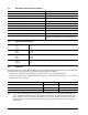
2.3 Recording and interface technology Interface Serial ATA (SATA) Recording method 16/17 EPRML Recording density BPI (bits/inch max) 790.7k Track density TPI (tracks/inch avg) 134.4k 2 Areal density (Gbits/inch avg) 106.35 Spindle speed (RPM) (± 0.
2.6 Start/stop times Power-on to Ready (sec) 10 (max) Standby to Ready (sec) 10 (max) Ready to spindle stop (sec) 12 (max) 2.7 Power specifications The drive receives DC power (+5V or +12V) through a native SATA power connector. See Figure 3 on page 16. 2.7.1 Power consumption Power requirements for the drives are listed in the table on page 9. Typical power measurements are based on an average of drives tested, under nominal conditions, using 5.0V and 12.
2.7.1.1 Typical current profile Figure 1. Typical 12V startup and operation current profile 2.7.2 Conducted noise Input noise ripple is measured at the host system power supply across an equivalent 80-ohm resistive load on the +12 volt line or an equivalent 15-ohm resistive load on the +5 volt line. • Using 12-volt power, the drive is expected to operate with a maximum of 120 mV peak-to-peak square-wave injected noise at up to 10 MHz.
2.7.4 Power-management modes The drive provides programmable power management to provide greater energy efficiency. In most systems, you can control power management through the system setup program.
2.8 Environmental specifications 2.8.1 Ambient temperature Ambient temperature is defined as the temperature of the environment immediately surrounding the drive. Actual drive case temperature should not exceed 69°C (156°F) within the operating ambient conditions. Above 1,000 feet (305 meters), the maximum temperature is derated linearly to 112°F (44°C) at 10,000 feet (3,048 meters). Operating: 0° to 60°C (32° to 140°F) Nonoperating: –40° to 70°C (–40° to 158°F) 2.8.
2.8.6 Vibration All vibration specifications assume that the drive is mounted securely with the input vibration applied at the drive mounting screws. Vibration may be applied in the X, Y or Z axis. 2.8.6.1 Operating vibration The maximum vibration levels that the drive may experience while meeting the performance standards specified in this document are specified below. 5–22 Hz 0.25 Gs (Limited displacement) 23–350 Hz 0.50 Gs 351–500 Hz 0.25 Gs 2.8.6.
2.
2.12 Agency certification 2.12.1 Safety certification The drives are recognized in accordance with UL 1950 and CSA C22.2 (950) and meet all applicable sections of IEC950 and EN 60950 as tested by TUV North America. 2.12.2 Electromagnetic compatibility Hard drives that display the CE mark comply with the European Union (EU) requirements specified in the Electromagnetic Compatibility Directive (89/336/EEC).
Radio and television interference. This equipment generates and uses radio frequency energy and if not installed and used in strict accordance with the manufacturer’s instructions, may cause interference to radio and television reception. This equipment is designed to provide reasonable protection against such interference in a residential installation. However, there is no guarantee that interference will not occur in a particular installation.
2.14 Corrosive environment Seagate electronic drive components pass accelerated corrosion testing equivalent to 10 years exposure to light industrial environments containing sulfurous gases, chlorine and nitric oxide, classes G and H per ASTM B845. However, this accelerated testing cannot duplicate every potential application environment.
14 NL35 Series 7200.2 SATA Product Manual, Rev.
3.0 Configuring and mounting the drive This section contains the specifications and instructions for configuring and mounting the drive. 3.1 Handling and static-discharge precautions After unpacking, and before installation, the drive may be exposed to potential handling and electrostatic discharge (ESD) hazards.
3.2 Configuring the drive Each drive on the Serial ATA interface connects in a point-to-point configuration with the Serial ATA host adapter. There is no master/slave relationship because each drive is considered a master in a point-to-point relationships. If two drives are attached on one Serial ATA host adapter, the host operating system views the two devices as if they were both “masters” on two separate ports. This means both drives behave as if they are Device 0 (master) devices.
3.4 Drive mounting You can mount the drive in any orientation using four screws in the side-mounting holes or four screws in the bottom-mounting holes. See Figure 4 on page 17 for drive mounting dimensions. Follow these important mounting precautions when mounting the drive: • Allow a minimum clearance of 0.030 inches (0.76 mm) around the entire perimeter of the drive for cooling. • Use only 6-32 UNC mounting screws. • The screws should be inserted no more than 0.150 inch (3.
18 NL35 Series 7200.2 SATA Product Manual, Rev.
4.0 Serial ATA (SATA) interface These drives use the industry-standard Serial ATA interface that supports FIS data transfers. It supports ATA programmed input/output (PIO) modes 0–4; multiword DMA modes 0–2, and Ultra DMA modes 0–6. For detailed information about the Serial ATA interface, refer to the “Serial ATA: High Speed Serialized AT Attachment” specification. 4.1 Hot-Plug compatibility NL35 Series 7200.
4.2 Serial ATA device plug connector pin definitions Table 4 summarizes the signals on the Serial ATA interface and power connectors.. Table 4: Segment Signal Serial ATA connector pin definitions Pin Function Definition S1 Ground 2nd mate S2 A+ Differential signal pair A from Phy S3 A- S4 Ground 2nd mate S5 B- Differential signal pair B from Phy S6 B+ S7 Ground 2nd mate Key and spacing separate signal and power segments Power P1 V33 3.3V power P2 V33 3.3V power P3 V33 3.
4.3 Supported ATA commands The following table lists Serial ATA standard commands that the drive supports. For a detailed description of the ATA commands, refer to the Serial ATA: High Speed Serialized AT Attachment specification. See “S.M.A.R.T. commands” on page 27.for details and subcommands used in the S.M.A.R.T. implementation.
Command name Command code (in hex) Security Erase Unit F4H Security Freeze F5H Security Set Password F1H Security Unlock F2H Seek 70H Set Features EFH Set Max Address F9H Note: Individual Set Max Address commands are identified by the value placed in the Set Max Features register as defined to the right. Address: Password: Lock: Unlock: Freeze Lock: Set Max Address Extended 37H Set Multiple Mode C6H Sleep 99H or E6H S.M.A.R.T. Disable Operations B0H / D9H S.M.A.R.T.
4.3.1 Identify Device command The Identify Device command (command code ECH) transfers information about the drive to the host following power up. The data is organized as a single 512-byte block of data, whose contents are shown in Table 5 on page 21. All reserved bits or words should be set to zero. Parameters listed with an “x” are drive-specific or vary with the state of the drive. See Section 2.0 on page 3 for default parameter settings.
Word Description Value 60–61 Total number of user-addressable LBA sectors available (see Section 2.1 for related information) *Note: The maximum value allowed in this field is: 0FFFFFFFh (268,435,455 sectors, 137 Gbytes). Drives with capacities over 137 Gbytes will have 0FFFFFFFh in this field and the actual number of useraddressable LBAs specified in words 100-103. This is required for drives that support the 48-bit addressing feature.
Word Description Value 129– 159 Seagate-reserved xxxxH 160– 254 ATA-reserved 0000H 255 Integrity word xxA5H Note. Advanced Power Management (APM) and Automatic Acoustic Management (AAM) features are not supported Note. See the bit descriptions below for words 63, 88, and 93 of the Identify Drive data. Description (if bit is set to 1) Bit Word 63 0 Multiword DMA mode 0 is supported. 1 Multiword DMA mode 1 is supported. 2 Multiword DMA mode 2 is supported.
4.3.2 Set Features command This command controls the implementation of various features that the drive supports. When the drive receives this command, it sets BSY, checks the contents of the Features register, clears BSY and generates an interrupt. If the value in the register does not represent a feature that the drive supports, the command is aborted. Power-on default has the read look-ahead and write caching features enabled.
4.3.3 S.M.A.R.T. commands S.M.A.R.T. provides near-term failure prediction for disc drives. When S.M.A.R.T. is enabled, the drive monitors predetermined drive attributes that are susceptible to degradation over time. If self-monitoring determines that a failure is likely, S.M.A.R.T. makes a status report available to the host. Not all failures are predictable. S.M.A.R.T. predictability is limited to the attributes the drive can monitor. For more information on S.M.A.R.T.
28 NL35 Series 7200.2 SATA Product Manual, Rev.
5.0 Seagate Technology support services Internet For information regarding Seagate products and services, visit www.seagate.com. Worldwide support is available 24 hours daily by email for your questions. Presales Support: Presales@Seagate.com Technical Support: DiscSupport@Seagate.com Warranty Support: http://www.seagate.com/support/service/index.html mySeagate my.seagate.com is the industry's first Web portal designed specifically for OEMs and distributors.
Customer Service Operations Warranty Service Seagate offers worldwide customer support for Seagate products. Seagate distributors, OEMs and other direct customers should contact their Seagate Customer Service Operations (CSO) representative for warrantyrelated issues. Resellers or end users of drive products should contact their place of purchase or Seagate warranty service for assistance. Have your serial number and model or part number available.
Index A ACA 11 acceleration 9 acoustics 9 Active 7 Active mode 7 actuator arm 5 AFR 10 Agency certification 11 altitude 8 Ambient temperature 8 ambient temperature 4, 5 Annualized Failure Rate 10 Areal density 4 ATA commands 21 Australia/New Zealand Standard AS/NZS3548 1995 11 Australian Communication Authority (ACA) 11 Australian C-Tick 11 Average latency 4 Average seek time 4 B buffer 4 Bytes per sector 3 C cables and connectors 16 Cache 4 capacity 3 case temperature 8 CE mark 11 certification 11 Check
Identify Device 21 Identify Device command 23 Idle 7, 21 Idle Immediate 21 Idle mode 5, 7 IEC950 11 Information Technology Equipment (ITE) 11 Initialize Device Parameters 21 Input noise ripple 6 input voltage 5 Interface 4 interface 19 Interleave 4 Internal data-transfer rate 4 is 4 ISO document 7779 9 ITE 11 K Korea Ministry of Information and Communication (MIC) 11 Korean RRL 11 L latency 4 latency time 5 LBA mode 3 logical geometry 3 M maintenance 10 master/slave 2 maximum temperature 8 MIC 11 mountin
S.M.A.R.T. Read Attribute Thresholds 22 S.M.A.R.T. Read Data 22 S.M.A.R.T. Read Log Sector 22 S.M.A.R.T. Return Status 22 S.M.A.R.T. Save Attribute Values 22 S.M.A.R.T.
34 NL35 Series 7200.2 SATA Product Manual, Rev.
Seagate Technology LLC 920 Disc Drive, Scotts Valley, California 95066-4544, USA Publication Number: 100390104, Rev.