Cheetah T10 SAS ST3300555SS ST3146755SS ST373355SS
©2006, Seagate Technology LLC All rights reserved Publication number: 100433694, A October 2006 Seagate, Seagate Technology, and the Seagate logo are registered trademarks of Seagate Technology LLC. SeaTools, SeaFONE, SeaBOARD, and SeaTDD are either registered trademarks or trademarks of Seagate Technology LLC. Other product names are registered trademarks or trademarks of their owners. Seagate reserves the right to change, without notice, product offerings or specifications.
Contents 1.0 Scope. . . . . . . . . . . . . . . . . . . . . . . . . . . . . . . . . . . . . . . . . . . . . . . . . . . . . . . . . . . . . . . . . . . . . . . . 1 2.0 Standards, compliance and reference documents . . . . . . . . . . . . . . . . . . . . . . . . . . . . . . . . . . . 2.1 Standards . . . . . . . . . . . . . . . . . . . . . . . . . . . . . . . . . . . . . . . . . . . . . . . . . . . . . . . . . . . . . . 2.1.1 Electromagnetic compatibility. . . . . . . . . . . . . . . . . . . . . . . . . .
6.4.1 Temperature . . . . . . . . . . . . . . . . . . . . . . . . . . . . . . . . . . . . . . . . . . . . . . . . . . . . 6.4.2 Relative humidity . . . . . . . . . . . . . . . . . . . . . . . . . . . . . . . . . . . . . . . . . . . . . . . . 6.4.3 Effective altitude (sea level) . . . . . . . . . . . . . . . . . . . . . . . . . . . . . . . . . . . . . . . . 6.4.4 Shock and vibration . . . . . . . . . . . . . . . . . . . . . . . . . . . . . . . . . . . . . . . . . . . . . . 6.4.5 Air cleanliness . . . . . . .
List of Figures Figure 1. Cheetah T10 SAS disc drive . . . . . . . . . . . . . . . . . . . . . . . . . . . . . . . . . . . . . . . . . . . . . . . . . . . . . . . . . . . . . .1 Figure 2. Typical ST3300555SS drive current profiles. . . . . . . . . . . . . . . . . . . . . . . . . . . . . . . . . . . . . . . . . . . . . . . . . .26 Figure 3. Typical ST3146755SS drive current profiles. . . . . . . . . . . . . . . . . . . . . . . . . . . . . . . . . . . . . . . . . . . . . . . . . .27 Figure 4.
2 Cheetah T10 SAS Product Manual, Rev.
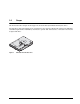
1.0 Scope This manual describes Seagate Technology® LLC, Cheetah® SAS (Serial Attached SCSI) disc drives. Cheetah drives support the SAS Protocol specifications to the extent described in this manual. The SAS Interface Manual (part number 100293071) describes the general SAS characteristics of Cheetah T10 and other Seagate SAS drives. Figure 1. Cheetah T10 SAS disc drive Cheetah T10 SAS Product Manual, Rev.
2 Cheetah T10 SAS Product Manual, Rev.
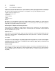
2.0 Standards, compliance and reference documents The drive has been developed as a system peripheral to the highest standards of design and construction. The drive depends on its host equipment to provide adequate power and environment for optimum performance and compliance with applicable industry and governmental regulations. Special attention must be given in the areas of safety, power distribution, shielding, audible noise control, and temperature regulation.
2.2 Compliance 2.2.1 Electromagnetic compliance Seagate uses an independent laboratory to confirm compliance with the directives/standards for CE Marking and C-Tick Marking. The drive was tested in a representative system for typical applications. The selected system represents the most popular characteristics for test platforms. The system configurations include: • • • • • • • Typical current use microprocessor 3.
2.3 Reference documents Cheetah T10 SAS Installation Guide Seagate part number: 100433695 SCSI Commands Reference Manual Seagate part number: 100293068 SAS Interface Manual Seagate part number: 100293071 Applicable ANSI SAS documents SFF-8323 SFF-8460 SFF-8470 SFF-8482 ANSI INCITS.xxx ISO/IEC 14776-xxx ISO/IEC 14776-xxx ISO/IEC 14776-xxx 3.
6 Cheetah T10 SAS Product Manual, Rev.
3.0 General description Cheetah drives combine giant magnetoresistive (GMR) heads, partial response/maximum likelihood (PRML) read channel electronics, embedded servo technology, and a Serial Attached SCSI (SAS) interface to provide high performance, high capacity data storage for a variety of systems including engineering workstations, network servers, mainframes, and supercomputers.
3.1 Standard features Cheetah drives have the following standard features: • • • • • • • • • • • • • • • • • • • • • • • • • • • 1.5 / 3 Gbit Serial Attached SCSI (SAS) interface Integrated dual port SAS controller supporting the SCSI protocol Support for SAS expanders and fanout adapters Firmware downloadable using the SAS interface 128-deep task set (queue) Supports up to 32 initiators Jumperless configuration.
3.4 Reliability • 1,400,000 hour MTBF (Annualized Failure Rate (AFR) of 0.62%) • Incorporates industry-standard Self-Monitoring Analysis and Reporting Technology (S.M.A.R.T.) • 5-year warranty 3.5 Formatted capacities Standard OEM models are formatted to 512 bytes per block. The block size is selectable at format time and must be a multiple of 4 bytes.
3.8 Options (factory installed) You may order the following items which are incorporated at the manufacturing facility during production or packaged before shipping. Some of the options available are (not an exhaustive list of possible options): • Other capacities can be ordered depending on sparing scheme and sector size requested. • Single-unit shipping pack. The drive is normally shipped in bulk packaging to provide maximum protection against transit damage.
4.0 Performance characteristics This section provides detailed information concerning performance-related characteristics and features of Cheetah drives. 4.1 Internal drive characteristics Drive capacity Read/write data heads Tracks per surface (total) Tracks per inch Peak bits per inch Areal Density Internal data rate Disc rotation speed Avg rotational latency ST3300555SS 300.0 8 74,340 125,000 890k 110 960 to 1607 15k 2.0 ST3146755SS 146.8 4 74,340 125,000 890k 110 960 to 1607 15k 2.
4.2.2 Format command execution time (minutes) Maximum (with verify) Maximum (without verify) ST3300555SS ST3146755SS ST373355SS 145 90 60 90 45 30 Execution time measured from receipt of the last byte of the Command Descriptor Block (CDB) to the request for a Status Byte Transfer to the Initiator (excluding connect/disconnect). 4.2.3 General performance characteristics Sustainable disc transfer rate*: Minimum 55.
The START STOP UNIT command may be used to command the drive to stop the spindle. Stop time is 30 seconds (maximum) from removal of DC power. There is no power control switch on the drive. 4.4 Prefetch/multi-segmented cache control The drive provides a prefetch (read look-ahead) and multi-segmented cache control algorithms that in many cases can enhance system performance. Cache refers to the drive buffer storage space when it is used in cache operations.
4.5.1 Caching write data Write caching is a write operation by the drive that makes use of a drive buffer storage area where the data to be written to the medium is stored while the drive performs the Write command. If read caching is enabled (RCD=0), then data written to the medium is retained in the cache to be made available for future read cache hits. The same buffer space and segmentation is used as set up for read functions.
5.0 Reliability specifications The following reliability specifications assume correct host and drive operational interface, including all interface timings, power supply voltages, environmental requirements and drive mounting constraints. Seek error rate: Read Error Rates1 Recovered Data Unrecovered Data Miscorrected Data Interface error rate: MTBF Preventive maintenance: 1.
5.1.3 Seek errors A seek error is defined as a failure of the drive to position the heads to the addressed track. After detecting an initial seek error, the drive automatically performs an error recovery process. If the error recovery process fails, a seek positioning error (Error code = 15h or 02h) will be reported with a Hardware error (04h) in the Sense Key. Recoverable seek errors are specified at Less than 10 errors in 108 seeks.
5.2.3 Hot plugging the drive When a disc is powered on by switching the power or hot plugged, the drive runs a self test before attempting to communicate on its’ interfaces. When the self test completes successfully, the drive initiates a Link Reset starting with OOB. An attached device should respond to the link reset. If the link reset attempt fails, or any time the drive looses sync, the drive initiated link reset. The drive will initiate link reset once per second but alternates between port A and B.
Reporting control Reporting is controlled by the MRIE bits in the Informational Exceptions Control mode page (1Ch). Subject to the reporting method, the firmware will issue to the host an 01-5Dxx sense code. The error code is preserved through bus resets and power cycles. Determining rate S.M.A.R.T. monitors the rate at which errors occur and signals a predictive failure if the rate of degraded errors increases to an unacceptable level.
be used to set this trip point. The default value for this drive is 68°C, however, you can set it to any value in the range of 0 to 68°C. If you specify a temperature greater than 68°C in this field, the temperature is rounded down to 68°C. A sense code is sent to the host to indicate the rounding of the parameter field. Table 1: Temperature Log Page (0Dh) Parameter Code Description 0000h Primary Temperature 0001h Reference Temperature 5.2.
5.2.6.2.1 State of the drive prior to testing The drive must be in a ready state before issuing the Send Diagnostic command. There are multiple reasons why a drive may not be ready, some of which are valid conditions, and not errors. For example, a drive may be in process of doing a format, or another DST. It is the responsibility of the host application to determine the “not ready” cause.
2. The Self-Test Results Value field is set to Fh 3. The drive will store the log page to non-volatile memory After a self-test is complete or has been aborted, the drive updates the Self-Test Results Value field in its SelfTest Results Log page in non-volatile memory. The host may use Log Sense to read the results from up to the last 20 self-tests performed by the drive. The self-test results value is a 4-bit field that reports the results of the test.
22 Cheetah T10 SAS Product Manual, Rev.
6.0 Physical/electrical specifications This section provides information relating to the physical and electrical characteristics of the drive. 6.1 AC power requirements None. 6.2 DC power requirements The voltage and current requirements for a single drive are shown below. Values indicated apply at the drive connector. Table 2: ST3300555SS DC power requirements ST3300555SS 1.
Table 3: ST3146755SS DC power requirements ST3146755SS 1.5 Gbit mode Notes Voltage ST3146755SS 3 Gbit mode (Amps) (Amps) (Amps) (Amps) +5V +12V [2] +5V +12V [2] Regulation [5] ±5% ±5% [2] ±5% ±5% [2] Avg idle current DCX [1] [6] 0.80 0.57 0.78 0.57 Maximum starting current (peak DC) DC 3σ [3] 0.87 2.12 0.87 1.93 (peak AC) AC 3σ [3] 1.20 3.49 1.21 3.45 [1] [4] 0.64 0.03 0.68 0.03 [1] 0.78 0.76 0.81 0.76 [1] 0.78 0.78 0.82 0.78 1.60 2.54 1.62 2.
[2] [3] [4] [5] [6] Degrees C ambient. For +12 V, a –10% tolerance is allowed during initial spindle start but must return to ±5% before reaching 15,000 RPM. The ±5% must be maintained after the drive signifies that its power-up sequence has been completed and that the drive is able to accept selection by the host initiator. See +12V current profile in Figures 2, 3, and 4. This condition occurs after OOB and Speed Negotiation completes but before the drive has received the Notify Spinup primitive.
Figure 2. 26 Typical ST3300555SS drive current profiles Cheetah T10 SAS Product Manual, Rev.
Figure 3. Typical ST3146755SS drive current profiles Cheetah T10 SAS Product Manual, Rev.
Figure 4. 28 Typical ST373355SS drive current profiles Cheetah T10 SAS Product Manual, Rev.
6.3 Power dissipation ST3300555SS in 3 Gbit operation Typical power dissipation under idle conditions in 3Gb operation is 14.22 watts (48.52 BTUs per hour). To obtain operating power for typical random read operations, refer to the following I/O rate curve (see Figure 5). Locate the typical I/O rate for a drive in your system on the horizontal axis and read the corresponding +5 volt current, +12 volt current, and total watts on the vertical axis. To calculate BTUs per hour, multiply watts by 3.4123.
ST3146755SS in 3 Gbit operation Typical power dissipation under idle conditions in 3Gb operation is 10.74 watts (36.65 BTUs per hour). To obtain operating power for typical random read operations, refer to the following I/O rate curve (see Figure 5). Locate the typical I/O rate for a drive in your system on the horizontal axis and read the corresponding +5 volt current, +12 volt current, and total watts on the vertical axis. To calculate BTUs per hour, multiply watts by 3.4123.
ST373355SS in 3 Gbit operation Typical power dissipation under idle conditions in 3Gb operation is 9.13 watts (31.15 BTUs per hour). To obtain operating power for typical random read operations, refer to the following I/O rate curve (see Figure 5). Locate the typical I/O rate for a drive in your system on the horizontal axis and read the corresponding +5 volt current, +12 volt current, and total watts on the vertical axis. To calculate BTUs per hour, multiply watts by 3.4123.
6.4 Environmental limits Temperature and humidity values experienced by the drive must be such that condensation does not occur on any drive part. Altitude and atmospheric pressure specifications are referenced to a standard day at 58.7°F (14.8°C). Maximum wet bulb temperature is 82°F (28°C). 6.4.1 Temperature a. Operating The maximum allowable continuous or sustained HDA case temperature for the rated MTBF is 122°F (50°C) The maximum allowable HDA case temperature is 60°C.
6.4.2 Relative humidity The values below assume that no condensation on the drive occurs. a. Operating 5% to 95% non-condensing relative humidity with a maximum gradient of 20% per hour. b. Non-operating 5% to 95% non-condensing relative humidity. 6.4.3 Effective altitude (sea level) a. Operating –1,000 to +10,000 feet (–305 to +3,048 meters) b. Non-operating –1,000 to +40,000 feet (–305 to +12,210 meters) 6.4.
d. Packaged Disc drives shipped as loose load (not palletized) general freight will be packaged to withstand drops from heights as defined in the table below. For additional details refer to Seagate specifications 30190-001 (under 100 lbs/45 kg) or 30191-001 (over 100 lbs/45 Kg). Package size Packaged/product weight Drop height <600 cu in (<9,800 cu cm) 600-1800 cu in (9,800-19,700 cu cm) >1800 cu in (>19,700 cu cm) >600 cu in (>9,800 cu cm) Any 0-20 lb (0 to 9.1 kg) 0-20 lb (0 to 9.1 kg) 20-40 lb (9.
6.4.4.2 Vibration a. Operating—normal The drive as installed for normal operation, shall comply with the complete specified performance while subjected to continuous vibration not exceeding 10-500 Hz @ 0.5 G (zero to peak) Vibration may be applied in the X, Y, or Z axis. Operating normal translational random flat profile 10 - 500 Hz 0.4 gRMS b.
6.4.7 Acoustics Sound power during idle mode shall be 3.6 bels typical when measured to ISO 7779 specification. Sound power while operating shall be 4.3 bels typical when measured to ISO 7779 specification. There will not be any discrete tones more than 10 dB above the masking noise on typical drives when measured according to Seagate specification 30553-001. There will not be any tones more than 24 dB above the masking noise on any drive. 6.4.8 Electromagnetic susceptibility See Section 2.1.1.1. 6.
7.0 Defect and error management Seagate continues to use innovative technologies to manage defects and errors. These technologies are designed to increase data integrity, perform drive self-maintenance, and validate proper drive operation. SCSI defect and error management involves drive internal defect/error management and SAS system error considerations (errors in communications between the initiator and the drive).
The drive firmware error recovery algorithms consists of 11 levels for read recoveries and five levels for write. Each level may consist of multiple steps, where a step is defined as a recovery function involving a single reread or re-write attempt. The maximum level used by the drive in LBA recovery is determined by the read and write retry counts. Table 5 equates the read and write retry count with the maximum possible recovery time for read and write recovery of individual LBAs.
7.3 SAS system errors Information on the reporting of operational errors or faults across the interface is given in the SAS Interface Manual. The SSP Response returns information to the host about numerous kinds of errors or faults. The Receive Diagnostic Results reports the results of diagnostic operations performed by the drive. Status returned by the drive to the initiator is described in the SAS Interface Manual.
7.6 Deferred Auto-Reallocation Deferred Auto-Reallocation (DAR) simplifies reallocation algorithms at the system level by allowing the drive to reallocate unreadable locations on a subsequent write command. Sites are marked for DAR during read operations performed by the drive. When a write command is received for an LBA marked for DAR, the auto-reallocation process is invoked and attempts to rewrite the data to the original location.
8.0 Installation Cheetah disc drive installation is a plug-and-play process. There are no jumpers, switches, or terminators on the drive. SAS drives are designed to be used in a host system that provides a SAS-compatible backplane with bays designed to accomodate the drive. In such systems, the host system typically provides a carrier or tray into which you need to mount the drive. Mount the drive to the carrier or tray provided by the host system using four 6-32 UNC screws.
8.2 Cooling Cabinet cooling must be designed by the customer so that the ambient temperature immediately surrounding the drive will not exceed temperature conditions specified in Section 6.4.1, "Temperature." The rack, cabinet, or drawer environment for the drive must provide heat removal from the electronics and head and disc assembly (HDA). You should confirm that adequate heat removal is provided using the temperature measurement guidelines described in Section 6.4.1.
8.3 Drive mounting Mount the drive using the bottom or side mounting holes. If you mount the drive using the bottom holes, ensure that you do not physically distort the drive by attempting to mount it on a stiff, non-flat surface. The allowable mounting surface stiffness is 80 lb/in (14.0 N/mm).
44 Cheetah T10 SAS Product Manual, Rev.
9.0 Interface requirements This section partially describes the interface requirements as implemented on Cheetah drives. Additional information is provided in the SAS Interface Manual (part number 100293071). 9.1 SAS features This section lists the SAS-specific features supported by Cheetah drives. 9.1.1 task management functions Table 6 lists the SAS task management functions supported.
9.2 Dual port support Cheetah SAS drives have two independent ports. These ports may be connected in the same or different SCSI domains. Each drive port has a unique SAS address. The two ports run at the same link rate. The first port to successfully complete speed negotiation sets the link rate support by both ports. When the second port participates in speed negotiation, it indicates the only supported speed is the speed selected by the first port.
9.3 SCSI commands supported Table 8 lists the SCSI commands supported by Cheetah drives.
Table 8: Commands supported by Cheetah T10 SAS family drives (continued) Command name Command code Supported Non-medium Error page (06h) Y Pages Supported list (00h) Y Read Error Counter page (03h) Y Read Reverse Error Counter page (04h) N Self-test Results page (10h) Y Background Medium Scan page (15h) Y Start-stop Cycle Counter page (0Eh) Y Temperature page (0Dh) Y Verify Error Counter page (05h) Y Write error counter page (02h) Y Mode Select (same pages as Mode Sense 1Ah) 15h Y
Table 8: Commands supported by Cheetah T10 SAS family drives (continued) Command name Command code Supported Reassign Blocks 07h Y Receive Diagnostic Results 1Ch Y Supported Diagnostics pages (00h) Y Translate page (40h) Y Release 17h Y Release (10) 57h Y Request Sense 03h Y Actual Retry Count bytes Y Extended Sense Y Field Pointer bytes Y Reserve 16h Y 3rd Party Reserve Y Extent Reservation N Reserve (10) 56h Y 3rd Party Reserve Y Extent Reservation N Rezero Unit
Table 8: Commands supported by Cheetah T10 SAS family drives (continued) Command name Command code FUA bit Supported Y Write Long 3Fh Y Write Same 41h Y PBdata N LBdata N XDRead 52h N XDWrite 50h N XPWrite 51h N [1] [2] [3] [4] 50 Cheetah drives can format to 512, 520, 524, or 528 bytes per logical block. Warning. Power loss during flash programming can result in firmware corruption. This usually makes the drive inoperable.
9.3.1 Inquiry data Table 9 lists the Inquiry command data that the drive should return to the initiator per the format given in the SAS Interface Manual.
Select command before the drive achieves operating speed and is “ready.” An attempt to do so results in a “Check Condition” status. On drives requiring unique saved values, the required unique saved values are stored into the saved values storage location on the media prior to shipping the drive. Some drives may have unique firmware with unique default values also.
Table 10: ST3300555SS Mode Sense data MODE DATA HEADER: 03 fa 00 10 00 00 00 08 BLOCK DESCRIPTOR: 22 ec b2 5c 00 00 02 00 MODE PAGES: DEF 81 0a c0 0b ff 00 00 00 05 00 ff ff CHG 81 0a ff ff 00 00 00 00 ff 00 ff ff DEF CHG 82 0e 00 00 00 00 00 00 00 00 01 3a 00 00 00 00 82 0e 00 00 00 00 00 00 00 00 ff ff 00 00 00 00 DEF CHG 83 16 68 58 00 00 00 38 00 00 03 db 02 00 00 01 00 e6 03 02 40 00 00 00 83 16 00 00 00 00 ff ff 00 00 00 00 00 00 00 00 00 00 00 00 00 00 00 00 DEF CHG 84 16 01 22 64 08 00 00 00
Table 11: ST3146755SS Mode Sense data MODE DATA HEADER: 03 fa 00 10 00 00 00 08 BLOCK DESCRIPTOR: 11 17 73 30 00 00 02 00 MODE PAGES: DEF CHG 81 0a c0 0b ff 00 00 00 05 00 ff ff 81 0a ff ff 00 00 00 00 ff 00 ff ff DEF CHG 82 0e 00 00 00 00 00 00 00 00 01 3a 00 00 00 00 82 0e 00 00 00 00 00 00 00 00 ff ff 00 00 00 00 DEF CHG 83 16 34 2c 00 00 00 1c 00 00 03 db 02 00 00 01 00 e6 03 02 40 00 00 00 83 16 00 00 00 00 ff ff 00 00 00 00 00 00 00 00 00 00 00 00 00 00 00 00 DEF CHG 84 16 01 22 64 04 00 00 0
Table 12: ST373355SS Mode Sense data MODE DATA HEADER: 03 fa 00 10 00 00 00 08 BLOCK DESCRIPTOR: 08 8b b9 98 00 00 02 00 MODE PAGES: DEF CHG 81 0a c0 0b ff 00 00 00 05 00 ff ff 81 0a ff ff 00 00 00 00 ff 00 ff ff DEF CHG 82 0e 00 00 00 00 00 00 00 00 01 3a 00 00 00 00 82 0e 00 00 00 00 00 00 00 00 ff ff 00 00 00 00 DEF CHG 83 16 1a 16 00 00 00 0e 00 00 03 db 02 00 00 01 00 e6 03 02 40 00 00 00 83 16 00 00 00 00 ff ff 00 00 00 00 00 00 00 00 00 00 00 00 00 00 00 00 DEF CHG 84 16 01 22 64 02 00 00 00
9.4 Miscellaneous operating features and conditions Table 13 lists various features and conditions. A “Y” in the support column indicates the feature or condition is supported. An “N” in the support column indicates the feature or condition is not supported.
9.4.1 SAS physical interface Figure 16 shows the location of the SAS device connector J1. Figures 17 and 18 provide the dimensions of the SAS device. Details of the physical, electrical, and logical characteristics are provided within this section. The operational aspects of Seagate’s SAS drives are provided in the SAS Interface Manual.. J6 SAS Interface connector Figure 16. Physical interface Cheetah T10 SAS Product Manual, Rev.
0.80 (6X) 5.92 7.62 4.65 0.52 2.00 (3X) 0.45 5.08 0.08 x 45 0.03 (7X) 0.10 M E 42.73 REF. 41.13 0.30 0.15 0.20 B 0.05 (2X) C A B 4.00 1.10 0.08 0.15 D 0.30 CL OF DATUM D 0.05 (4X) A B R0.30 C 0.08 (4X) SEE Detail1 33.43 0.05 B 15.875 15.875 1.27 (14X) 1.27 (6X) 0.84 5.08 0.05 (22X) 0.15 B 4.90 0.08 0.35MIN P15 P1 S7 S1 CL OF DATUM B Figure 17. 58 SAS connector dimensions Cheetah T10 SAS Product Manual, Rev.
Detail A 6.10 S14 2.25 S8 0.05 x 45 (5X) 0.05 0.40 4.85 0.30 0.05 0.10 B 0.05 X 45 (3X) CORING ALLOWED IN THIS AREA. E 4.40 0.15 R0.30 0.08 SEE Detail 2 C 1.95 0.08 A 45 0.35 3.90 0.05 0.15 SECTION C - C SECTION A - A 0.08 0.05 CONTACT SURFACE FLUSH TO DATUM A 0.03 65 1.23 0.05 0.08 1.90 0.08 30 0.05 Detail 2 2.40 0.08 0.10 A SECTION B - B D Figure 18. SAS connector dimensions 9.4.2 Physical characteristics This section defines physical interface connector. 9.4.
9.4.4 Electrical description SAS drives use the device connector for: • DC power • SAS interface • Activity LED This connector is designed to either plug directly into a backpanel or accept cables. 9.4.5 Pin descriptions This section provides a pin-out of the SAS device and a description of the functions provided by the pins. Table 15: SAS pin descriptions Pin Signal name S1 Port A Ground S2* +Port A_in S3* Signal type Pin Signal name P1* NC (reserved 3.3Volts) P2* NC (reserved 3.
9.4.6 SAS transmitters and receivers A typical SAS differential copper transmitter and receiver pair is shown in Figure 19. The receiver is AC coupling to eliminate ground shift noise. TX .01 RX .01 Receiver 100 RY Differential Transfer Medium Transmitter 100 TY Figure 19. SAS transmitters and receivers 9.4.7 Power The drive receives power (+5 volts and +12 volts) through the SAS device connector. Three +12 volt pins provide power to the drive, 2 short and 1 long.
The Ready LED Out signal is designed to pull down the cathode of an LED. The anode is attached to the proper +3.3 volt supply through an appropriate current limiting resistor. The LED and the current limiting resistor are external to the drive. See Table 17 for the output characteristics of the LED drive signals. Table 17: LED drive signal State Test condition Output voltage LED off, high 0 V ≤ VOH ≤ 3.6 V -100 µA < IOH < 100 µA LED on, low IOL = 15 mA 0 ≤ VOL ≤ 0.225 V 9.5.
9.5.2.1.2 Receive eye mask Figure 20 describes the receive eye mask. This eye mask applies to jitter after the application of a single pole high-pass frequency-weighting function that progressively attenuates jitter at 20 dB/decade below a frequency of ((bit rate) / 1.667). Absolute amplitude (in V) Z2 Z1 0V -Z1 -Z2 0 X1 X2 1-X1 1-X2 1 Normalized time (in UI) Figure 20.
The leading and trailing edge slopes of figure 20 shall be preserved.
9.5.2.2 Transmitter signal characteristics Table 19 specifies the signal requirements at the transmitter end of a TxRx connection as measured into the zero-length test load. All specifications are based on differential measurements. The OOB sequence is performed at signal voltage levels corresponding to the lowest supported transfer rate. Table 19 specifies the signal characteristics. Table 19: Transmitter signal characteristics Signal characteristica Units 1.5 Gbps 3.
9.5.2.3 Receiver signal characteristics Table 20 defines the compliance point requirements of the signal at the receiver end of a TxRx connection as measured into the test loads specified in figure 23 and figure 24. Table 20: Receiver signal characteristics Signal characteristic Units 1.5 Gbps 3.0 Gbps Jitter (see figure 20)b N/A See table 21 See table 21 2 x Z2 mV(P-P) 1,200 1,600 2 x Z1 mV(P-P) 325 275 UI 0.275 0.275 X2 UI 0.50 0.50 Skewd ps 80 75 mV(P-P) 2.000 2.
9.5.2.3.2 Receiver jitter tolerance Table 22 defines the amount of jitter the receiver shall tolerate . Table 22: Receiver jitter tolerance 1.5 Gbpsa 3.0 Gbpsa Sinusoidal jitterb,c Deterministic jittere,f,h Total jitterh Sinusoidal jitterb,d Deterministic jittere,g,h Total jitterh 0.10 0.35 0.65 0.10 0.35 0.65 a Units are in UI.
Table 23: Impedance requirements (Sheet 2 of 2) Requirement Common mode impedanceb,e Units 1.5 Gbps 3.0 Gbps ohm 20 min/40 max 20 min/40 max ohm 60 min/115 max 60 min/115 max ohm 5 5 ohm 15 min/40 max 15 min/40 max Transmitter source termination Differential impedanceb Differential impedance imbalanceb,g b Common mode impedance a All times indicated for time domain reflectometer measurements are recorded times.
A combination of a zero-length test load and the transmitter compliance transfer function (TCTF) test load methodology is used for the specification of transmitter characteristics. This methodology specifies the transmitter signal at the test points on the required test loads. The transmitter uses the same settings (e.g., preemphasis, voltage swing) with both the zero-length test load and the TCTF test load. The signal specifications at IR are met under each of these loading conditions.
Figure 24 shows the zero-length test load. 50 ohm 10 nF Tx+ Probe points 50 ohm 10 nF Tx- SAS internal connector Figure 24. Zero-length test load Figure 25 shows an ISI loss example at 3.0 Gbps. S21 (dB) Compliance interconnect magnitude response and ISI loss example for 3.0 Gbps 0 ISI loss > 3.9 dB -10.9 dB Sample compliance interconnect 0.3 1.5 Figure 25. Frequency (GHz) 3.0 ISI loss example at 3.0 Gbps Figure 26 shows an ISI loss example at 1.5 Gbps.
9.5.2.5 Receiver characteristics The drive receiver is A.C. coupled. The receive network terminates the TxRx connection by a 100 ohm equivalent impedance as specified in table 23. The receiver operates within a BER of 10-12 when a SAS signal with valid voltage and timing characteristics is delivered to the compliance point from a 100 ohm source. The received SAS signal are considered valid if it meets the voltage and timing limits specified in table 20.
72 Cheetah T10 SAS Product Manual, Rev.
10.0 Seagate Technology support services Online services Internet www.seagate.com for information about Seagate products and services. Worldwide support is available 24 hours daily by e-mail for your questions. Presales Support: www.seagate.com/support/email/email_presales.html or Presales@Seagate.com Technical Support: www.seagate.com/support/email/email_disc_support.html or DiscSupport@Seagate.com mySeagate my.seagate.
Data Recovery Services Seagate offers data recovery services for all formats and all brands of storage media. Our Data Recovery Services labs are currently located in North America. To speak with a case management representative, call 1-800-475-0143. Additional information, including an online request form and data loss prevention resources, is available at www.datarecovery.seagate.com. Authorized Service Centers In some locations outside the US, you can contact an Authorized Service Center for service.
European support services For presales and technical support in Europe, dial the Seagate Service Center toll-free number for your specific location. If your location is not listed here, dial our presales and technical support call center at +1-405324-4714 from 8:00 A.M. to 11:45 A.M. and 1:00 P.M. to 5:00 P.M. (Central Europe time) Monday through Friday. The presales and technical support call center is located in Oklahoma City, USA.
Africa/Middle East support services For presales and technical support in Africa and the Middle East, dial our presales and technical support call center at +1-405-324-4714 from 8:00 A.M. to 11:45 A.M. and 1:00 P.M. to 5:00 P.M. (Central Europe time) Monday through Friday. The presales and technical support call center is located in Oklahoma City, USA. For warranty service in Africa and the Middle East, dial our European CSO warranty center at +31-20-3167222 from 8:30 A.M. to 5:00 P.M.
Index Numerics 12 volt pins 61 5 volt pins 61 A abort task set function 45 AC coupling 61 AC power requirements 23 ACA active status 56 ACA active, faulted initiator status 56 acoustics 36 active LED Out signal 61 actuator assembly design 7 adaptive caching 56 AFR 9 air cleanliness 35 air flow 42 illustrated 42 air inlet 42 altitude 33 ambient 32 ambient temperature 42 ANSI documents SCSI 5 Serial Attached SCSI 5 asynchronous event notification 56 audible noise 3 auto write and read reallocation programmab
environment 42 environmental limits 32 requirements 15 environmental control 35 error management 37 rates 15 errors 37 requirements 45 intermediate/condition met/good status 56 intermediate/good status 56 internal data rate 11 internal defects/errors 37 internal drive characteristics 11 IRAW 40 F jumpers 41 FCC rules and regulations 3 features 8 interface 45 firmware 8 corruption 50 flawed sector reallocation 8 Format command execution time 12 function complete, code 00 45 not supported, code 05 45 reje
N noise audible 3 noise immunity 25 non-operating 33, 35 temperature 32 non-operating vibration 35 O office environment 35 operating 33, 35 operating environment 16 option selection 60 out-of-plane distortion 43 P package size 34 package test specification 5 packaged 34 parameter rounding 56 PCBA 43 peak bits per inch 11 peak operating current 23, 24 peak-to-peak measurements 25 performance characteristics detailed 11 general 12 performance degradation 33 performance highlights 8 physical damage 35 physic
surface stiffness allowable for non-flat surface 43 switches 41 synchronized spindle operation 56 system chassis 43 T task management functions 45 Abort task set 45 Clear ACA 45 Clear task set 45 terminate task 45 task management response codes 45 Function complete 00 45 Function not supported 05 45 Function reject 04 45 task set full status 56 technical support services 73 temperature 32, 42 limits 32 non-operating 32 regulation 3 See also cooling terminate task function 45 terminators 41 tracks per inch
Seagate Technology LLC 920 Disc Drive, Scotts Valley, California 95066-4544, USA Publication Number: 100433694, Rev.