○ ○ ○ ○ ○ ○ ○ ○ ○ ○ ○ ○ ○ ○ ○ ○ ○ ○ ○ ○ ○ ○ ○ ○ ○ ○ ○ ○ ○ ○ ○ ○ ○ ○ ○ Elite 9 Disc Drive ○ ○ ○ ○ ○ ○ ○ ○ ○ ○ ○ ○ ○ ○ ○ ○ ○ ○ ○ ○ ○ ○ ○ ○ ○ ○ ○ ○ ○ ○ ○ ○ ○ ○ ○ ○ ○ ○ ○ ○ ○ ○ ○ ○ ○ ○ ○ ○ ○ ○ ○ ○ ○ ○ ○ ○ ○ ○ ○ ST410800N/ND ○ ○ ○ ○ ○ ○ ○ ○ ○ ○ ○ ST410800W/WD ○ ○ ○ ○ ○ ○ ○ ○ ○ ○ ○ ○ ○ ○ ○ ○ ○ ○ ○ ○ ○ ○ ○ ○ ○ ○ ○ ○ ○ ○ ○ ○ ○ ○ ○ ○ ○ ○ ○ ○ ○ ○ ○ ○ ○ ○ ○ ○ ○ ○ ○
Elite 9 Installation Guide, Rev. B Contents Preface .................................................................. Electrostatic discharge protection ........................... Important safety information and precautions ......... Wichtige Sicherheitshinweise ............................... Technical support services ..................................... General description ................................................ Initial setup information ...........................................
Elite 9 Installation Guide, Rev. B 1 Preface This manual contains information for users of Seagate® Elite™ 9 SCSI disc drives. It provides support services, performance specifications, and initial setup information. Additional information is available in the Elite 9 Product Manual (part number 83328860). Contact your Seagate sales representative if you need to order this publication. Electrostatic discharge protection Caution.
2 Elite 9 Installation Guide, Rev. B • Ground yourself to the drive whenever the drive electronics are or will be exposed. Connect yourself to ground with a wrist strap (Seagate part number 12263496). Connection may be made to any grounded metal assembly. As a general rule, remember that you and the drive electronics must all be grounded to avoid potentially damaging static discharges. • Turn off the power before removing or installing the DC power cable. • Do not remove any circuit boards from the drive.
Elite 9 Installation Guide, Rev. B 3 read and followed to minimize or eliminate the risk of personal injury. The warnings point out conditions or practices that may endanger you or others. The cautions point out conditions or practices that may damage the unit, possibly making it unsafe for use. These warnings and cautions are not exhaustive. We cannot possibly know, evaluate, and advise you of all the ways in which maintenance might be performed or the possible risk of each technique.
4 Elite 9 Installation Guide, Rev. B • Ensure that the internal temperature of the rack or cabinet does not exceed the limits defined for the drive when the drive is mounted in an equipment rack or cabinet. When units are stacked vertically, pay attention to the top where temperatures are usually highest. • Follow the precautions listed above in “Electrostatic discharge protection.” • Do not remove any circuit boards from the drive chassis.
Elite 9 Installation Guide, Rev. B 5 dards. Typical applications of these disc drives include customer packaging and subsystem design. Safety agencies conditionally certify component assemblies, such as the Elite disc drive, based on their final acceptability in the end-use product. The subsystem designers are responsible for meeting these conditions of acceptability in obtaining safety/regulatory agency compliancein their end-use products and for certifying where required by law.
6 Elite 9 Installation Guide, Rev. B dürfen nur von qualifiziertem Fachpersonal vorgenommen werden. Wir empfehlen die Verfahren in diesem Handbuch als effektive Methoden zur Wartung und Reparatur der Einheit. Einige Verfahren erfordern Spezialwerkzeuge; diese müssen zur sachgemäßen Ausführung der Wartungsarbeiten und aus Sicherheitsgründen den Empfehlungen entsprechend verwendet werden. Die Verfahren in diesem Handbuch und die Aufkleber auf dem Gerät enthalten Warn- und Vorsichtshinweise.
Elite 9 Installation Guide, Rev. B 7 zuerst sicher, daß das gewählte Verfahren weder Ihre persönliche Sicherheit noch die Leistung der Einheit gefährdet. Beachten Sie in jedem Fall die folgenden Warn-und Vorsichtshinweise: • Führen Sie alle Wartungsarbeiten entsprechend den Anweisungen in diesem Handbuch aus. • Beachten Sie alle Warn- und Vorsichtshinweise in diesem Handbuch. • Treffen Sie beim Betrieb oder bei der Reparatur der Einheit angemessene Sicherheitsvorkehrungen.
8 Elite 9 Installation Guide, Rev. B • Befolgen Sie die oben unter “Electrostatic Discharge Protection” angegebenen Sicherheitsmaßnahmen. • Nehmen Sie keine Platinen aus dem Laufwerkgehäuse. Wenn eine Platine defekt ist, muß das gesamte Laufwerk zur Reparatur eingeschickt werden. Die Herausnahme von Platinen durch andere Personen als die für die werkseitige Reparatur zuständigen kann zu einer Beschädigung der Komponenten und Erlöschen des Garantieanspruchs führen.
Elite 9 Installation Guide, Rev. B 9 geltenden Standards zu gewährleisten. Zu den typischen Anwendungen dieser Festplattenwerke zählen Systemeinbau durch den Kunden und die Konstruktion von Untersystemen. Sicherheitsbehörden gewähren eine bedingte Zulassung für Komponenten wie das EliteFestplattenlaufwerk vorbehaltlich der endgültigen Zulassung im Endprodukt.
10 Elite 9 Installation Guide, Rev. B Technical support services Seagate Technology provides technical support literature and diagnostic utilities to authorized distributors. Please contact your dealer for technical support and installation troubleshooting. Product technical support is available for all Seagate products by calling the SeaFAX™, SeaFONE™, SeaTDD™, or SeaBOARD™ services. These are toll calls if you dial from outside of the number’s local dialing area.
Elite 9 Installation Guide, Rev. B 11 access this service, which is available from 8:00 A.M. to 5:00 P.M. PST, Monday through Friday. SeaBOARD: The Seagate Technical Support Bulletin Board System (BBS) is available 24 hours a day, 7 days a week. A modem is required to access this service. The communications software must be set for 8 data bits, no parity, and 1 stop bit (8N1). All BBS numbers operate at 9600 baud max.
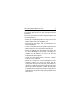
12 Elite 9 Installation Guide, Rev. B General description Elite 9 SCSI disc drives are high capacity, randomaccess digital-data storage devices. An Elite 9 drive is illustrated in Figure 1. Specifications and DC power requirements for the drive are listed in a table following the figure. The drive is a component for installation in an enclosure designed for the drive. This is often a rack within the system or an external enclosure designed to house one or more disc drives or other peripheral units.
Elite 9 Installation Guide, Rev. B 13 J4A J01 J4B SCSI I/O Connector DC Power Connector Figure 1.
14 Elite 9 Installation Guide, Rev.
Elite 9 Installation Guide, Rev. B 15 DC power requirements for ST410800N/ND drives Voltage regulation5 Max operating current DC 3σ 1 Single-ended Differential + 5V11 +12V +5V11 + 12V 2 ± 5% ± 5% ± 5% ± 5%2 Amps 0.95 1.85 1.4 1.85 Avg idle current DC X 1, 12 0.665 1.57 0.71 1.57 Max starting current Peak DC 3σ 3, 6 Peak AC 3σ 3 0.98 – 4.8 5.12 1.0 – 4.8 5.12 Delay motor start Max DC 3σ 1, 4 0.98 0.25 1.0 0.25 Peak operating current Typical DC X 1, 10 Max DC 3σ 1 Max (peak) AC 3σ 0.
16 Elite 9 Installation Guide, Rev. B DC power requirements for ST410800W/WD drives Single ended 5V[11] 12V ± 5% ± 5%[2] Voltage regulation[5] Amps Max operating current DC 3σ 1 Avg idle current DC X Differential 5V[11] 12V ±5% ± 5%[2] 1, 12 1.0 1.94 1.27 1.94 0.7 1.56 1.0 1.56 Max starting current Peak DC 3σ 3, 6 Peak AC 3σ 3 1.0 – 4.8 5.12 1.1 – 4.8 5.12 Delay motor start Max DC 3σ 1, 4 0.96 0.25 1.1 0.25 Peak operating current Typical DC X 1, 15 Max DC 3σ 1 Max (peak) AC 3σ 0.
Elite 9 Installation Guide, Rev. B 1 17 Measured with an average reading DC ammeter. Instantaneous +12V current peaks will exceed these values. 2 A −10% tolerance is permissible during initial start of the spindle but must return to ±5% before reaching 5,400 RPM. The ±5% must be maintained after the drive signifies that its power-up sequence has been completed and that it can accept selection by the host initiator. 3 See the +12V current profile in the Elite 9 Product Manual.
18 Elite 9 Installation Guide, Rev. B continued from previous page 12 All power-saving features are enabled. 13 Seeking is defined as a third-stroke seek at OD. A command is issued every 23 msec. 14 Read track is defined as repeat reads of track 15 with an 88% duty cycle. 15 Operating condition is a third-stroke seek at OD and read 1 track. A command is issued every 60 msec for ST410800W drives and every 72 msec for ST410800WD drives.
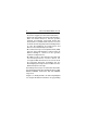
Elite 9 Installation Guide, Rev. B 19 Setting the SCSI ID jumpers Each device on the SCSI chain must have a unique SCSI ID. The host system’s SCSI controller usually uses the highest-numbered ID available (ID7 in non-wide systems); therefore the lower-numbered SCSI IDs are normally used for the other SCSI devices such as this Elite disc drive. Note. Most SCSI controllers (host adapters) allow you to skip a SCSI ID. For example, you can have ID0, ID1, and ID3 (skipping ID2).
20 Elite 9 Installation Guide, Rev. B J4A SCSI I/O Connector J01 J4B DC Power Connector J4A Pin 1 SCSI ID = 0 (factory setting) SCSI ID = 1 SCSI ID = 2 SCSI ID = 3 SCSI ID = 4 SCSI ID = 5 SCSI ID = 6 SCSI ID = 7 SCSI ID = 8* SCSI ID = 9* SCSI ID = Ah (10)* SCSI ID = Bh (11)* SCSI ID = Ch (12)* SCSI ID = Dh (13)* SCSI ID = Eh (14)* SCSI ID = Fh (15)* *Applicable only for W- and WD-type drives. Figure 2.
Elite 9 Installation Guide, Rev. B 21 Terminating the drive If you are installing the drive in a system that has other SCSI devices installed, terminate only the end devices on the SCSI chain. A SCSI “device” is any disc drive, scanner, tape backup unit, or other piece of hardware connected to your system using the SCSI bus. The top example in Figure 3 shows an internal hard disc at one end of the SCSI bus with the SCSI controller at the other end (both are terminated).
22 Elite 9 Installation Guide, Rev. B To terminate ST410800N and ST410800W drives, enable the permanently mounted IC terminators by installing a jumper on J4A pins 19 and 20 as shown inFigure 4. If you install one of these models and it is not on the end of the SCSI bus, remove internal termination from the drive by removing the Enable Drive Terminator jumper (see Figure 4). This disables the permanently mounted IC terminators. Note. This jumper applies only to N- and W-type models.
Elite 9 Installation Guide, Rev. B 23 ST410800ND and ST410800WD (differential) drives are shipped with terminators (part number 15479501) installed on the circuit board. Figure 5 illustrates the locations of the terminators. To remove termination from the drive, carefully lift the terminators from their sockets. ST410800ND Non-wide I/O Connector I/O Terminating Resistors ST410800WD Wide I/O Connector I/O Terminating Resistors Figure 5.
24 Elite 9 Installation Guide, Rev. B Pin 2 Pin 4 Pin 3 Pin 1 J01 4 Terminator J01 2 Power Option Internal terminator power source (factory setting) External terminator power source Internal terminator power to I/O 3 1 Figure 6. Setting terminator power jumpers (ST410800N shown) Changing other applicable jumper options Elite 9 drives are designed for use in a variety of systems.
Elite 9 Installation Guide, Rev. B J4A SCSI I/O Connector J01 J4B DC Power Connector J4A Pin 1 Write Protect Write Enable (factory setting) Reserved LED Connections Connect the anode to the desired LED connector and the cathode to the ground pin. Active LED connector (+) Ready LED connector (+) Fault LED connector (+) Ground (–) J4B Pin 1 Spinup Delay Option Immediate spinup. Valid only if the Start Command Option jumper is disconnected.
26 Elite 9 Installation Guide, Rev. B Synchronizing spindles in multiple drive configurations If you are installing two or more Elite 9 drives, you may (optionally) synchronize their spindles to reduce the latency associated with switching from one drive to another. Spindle sync cables are used to connect the drives. Use pins 23 and 24 on the J4A connector to attach the spindle sync cable. Pin 24 provides the reference index signal (SSREF+) and pin 23 provides ground (GND). See Figure 8.
Elite 9 Installation Guide, Rev. B 27 Figure 9 illustrates a typical synchronized spindle configuration. After connecting each drive with spindle sync cables, you must designate a master spindle sync reference source. This master source is normally a disc drive located on the same SCSI bus as the other drives you want to synchronize with. To designate a drive as the master, use SCSI interface commands. Refer to the Product Manual for information about using these commands.
28 Elite 9 Installation Guide, Rev. B Providing adequate cooling The enclosure design must ensure adequate cooling for the drive. The maximum ambient temperature is 45oC. The drive’s product manual (83328860) describes how to evaluate the air-flow design. The evaluation consists of ensuring that the case temperature of certain critical components remains within acceptable limits during drive operation.
Elite 9 Installation Guide, Rev. B 29 Kühlung des Systems Die Gehäusekonstruktion muß eine ausreichende Kühlung des Laufwerkes gewährleisten. Die Umgebungstemperatur darf maximal 45oC betragen. Die Produkthandbuch Elite 9 (Dokument 83328860) enthalten Anweisungen zur Beurteilung der Luftstromkonstruktion. Die Beurteilung muß sicherstellen, daß sich die Gehäusetemperatur bestimmter kritischer Komponenten bei Laufwerkbetrieb innerhalb zugelassener Grenzen hält.
30 Elite 9 Installation Guide, Rev. B Above unit Über der Einheit Under unit Unter der Einheit Note. Air flows in the direction shown (front to back) or in reverse direction (back to front) Hinweis. Luftstrom in der angezeigten Richtung (von vorne nach hinten) oder in umgekehrter Richtung (von hinten nach vorne) Above unit Über der Einheit Under unit Note. Air flows in the direction shown or Unter der Einheit in reverse direction (side to side) Hinweis.
Elite 9 Installation Guide, Rev. B 31 Mounting the drive and connecting cables Do not touch the connector pins or any components on the control board without observing static-discharge precautions. Always handle the drive by the frame only. The drive may be mounted in any orientation (horizontally, vertically, and any combination thereof); however, you must ensure that the drive receives adequate air flow for cooling. 1. Mount the drive to the host system’s chassis using four 6-32 UNC screws.
32 Elite 9 Installation Guide, Rev. B Installation des Laufwerkes und Anschluß der Kabel Beachten Sie beim Handhaben und Anfassen der Anschlußstifte und Komponenten die Vorsichtsmaßnahmen zur Verhinderung statischer Aufladung. Fassen Sie das Laufwerk nur am Rahmen an. Das Laufwerk kann in beliebiger Orientierung (horizontal, vertikal oder schräg) installiert werden; jedoch muß dafür gesorgt werden, daß ein ausreichender Luftstrom zur Kühlung des Laufwerkes vorhanden ist. 1.
Elite 9 Installation Guide, Rev. B 33 M4 x .70 Metric Threads (4) 1 1 6-32 Threads (4) Side A C.G. K B D E C F J Bottom I 1 6-32 Threads (4) G H C.G. L I in 1 The maximum screw depth that extends into chassis must not exceed 0.14 inches. Screws must not touch the module or interfere with the sway space. A B C D E F G H I J K L 3.25 0.86 0.39 1.93 3.120 8.06 5.50 5.75 0.12 3.90 1.55 3.15 ± 0.01 ± 0.01 ± 0.01 ± 0.01 ± 0.005 max ± 0.01 ± 0.01 ± 0.01 ± 0.05 ± 0.05 ± 0.05 Figure 11.
34 Elite 9 Installation Guide, Rev. B 2. Verify that all connections between the drive and the host system are correctly installed. 2. Prüfen Sie, ob alle Verbindungen zwischen dem Laufwerk und dem Host-System korrekt hergestellt sind. 3. Verify that you have correctly installed SCSI ID jumpers and that you have properly terminated the SCSI bus (see Figures 2, 3, 4, 5, and 6). 3. Stellen Sie sicher, daß die SCSI-Kennungsbrncken und die Abschlußwiderstände, soweit erforderlich, korrekt installiert sind.
Elite 9 Installation Guide, Rev. B 35 4. Schließen Sie das 50-polige SCSI-Kabel an den SCSI-Steckverbinder des Laufwerkes an (wie bereits in Abbildung 1 gezeigt). Das Kabel darf nicht gedehnt oder gedrückt werden und es darf den Luftstrom zur Kühlung des Systems nicht behindern. Das Laufwerk wird über einen 4-poligen, neben dem SCSI-Anschluß befestigten Steckverbinder mit Gleichstrom versorgt. Der Ausgang eines Netzteils muß SELV (safety extra low voltage) nach IEC 950 entsprechen.
36 Elite 9 Installation Guide, Rev. B Note. Signal ground on the power control board (PCB) and the head and disc assembly (HDA) are connected together in this drive and you cannot separate them. The equipment in which you have mounted the drive is connected directly to the HDA and PCB without electrically isolating shock mounts. Maximizing the conductive contact area between HDA ground and system ground may reduce radiated emissions.
Elite 9 Installation Guide, Rev. B 37 Systemgehäuse nicht an die HDA/PCB-Erdung anschließen wollen, müssen Sie das Laufwerk auf nichtleitende Weise (galvanisch isoliert) im HostSystem einbauen. Die daraus u.U. resultierende verstärkte elektromagnetische Strahlung fällt in den Zuständigkeitsbereich des Systemdesigners. 5. Replace the host system’s cover. 5. Setzen Sie das Gehäuseoberteil des Host-Systems wieder auf. Formatting the drive Warning. Formatting a drive erases all user data.
38 Elite 9 Installation Guide, Rev. B Seagate Technology, Inc. 920 Disc Drive, Scotts Valley, CA 95066-4544, USA Publication Number: 83328850, Rev.