............................. Elite Disc Drive ............................. ST43400N/ND ............................. ............................. User’s Manual .............................
ii Contents Preface .................................................................................................... Electrostatic discharge protection ........................................................ Important safety information and precautions ...................................... Technical support services .................................................................. Section 1. General description ................................................................ Section 2.
ST43400N/ND User’s Manual iii Preface This manual contains information for users of the Seagate ST43400N and ST43400ND Elite disc drives employing the SCSI interface. It provides installation, operation, and maintenance information. This manual also lists the part numbers for options and accessories available for these drives. Additional information is available in the reference manual (publication 83327640). Electrostatic discharge protection Caution.
iv Important safety information and precautions Caution. Use forced-air ventilation when bench-testing the drive to ensure proper cooling of drive components. Use proper safety and repair techniques for safe, reliable operation of this unit. Service should be done only by qualified persons. We recommend the procedures in this manual as effective ways of servicing the unit. Some procedures require the use of special tools. For proper maintenance and safety, you must use these tools as recommended.
ST43400N/ND User’s Manual v • Do not remove the head and disc assembly (HDA) from the drive chassis. Return the entire drive for depot repair if the HDA is defective. • Do not attempt to disassemble the HDA. It is not field repairable. If the sealed HDA is opened by personnel not performing depot repair, this will damage components and void the warranty. As a component, this drive is designed to be installed and operated in accordance with UL1950, IEC950, EN60950, CSA C22.2 950, and VDE0806.
vi Technical support services Seagate Technology provides technical support literature and diagnostic utilities to authorized distributors. Please contact your dealer for technical support and installation troubleshooting. Product technical support is available for all Seagate products by calling the SeaFAX, SeaFONE, or SeaBOARD services. These are toll calls if you dial from outside of the number’s local dialing area.
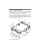
1 Section 1. General description The Seagate ST43400N/ND Elite 3 disc drives are high speed, random access digital data storage devices. They communicate with an initiator using the Small Computer System Interface (SCSI). The drive is shown in Figure 1, and its specifications are listed in Table 1 on the following page. The drive is a component for installation in an enclosure designed for the drive.
2 Table 1. Drive specifications Characteristics Conditions Specifications Size Dimensions See “Space requirements” in section 2 Weight (drive only) 3.6 kg (8.0 lb) Weight (power supply only) 2.3 kg (5.
General description 3 continued from previous page Characteristics Conditions SCSI transfer rate, burst Specifications 10.0 Mbytes/sec max Seek time (time required to move heads to a different track address— excluding SCSI I/O overhead) Typical full 23.5 msec Typical average 11.5 msec Typical one-track 1.7 msec Typical access times Write Read Typical single track seek msec 1.7 0.9 Average seek msec 11.5 10.5 Maximum seek msec 23.5 22.5 Average 5.
4 The drive contains all the circuits and mechanical devices necessary to record data on and recover it from its discs. The drive requires DC voltage input from an external power supply, which receives its AC input power from the site main power source. A power supply and DC power cable are available accessories. The drive consists of a head and disc assembly (HDA) and two circuit boards, mounted on a common chassis. The circuit boards contain the electronics required for drive operation.
General description 5 Unit Selection Logic Data recorded in concentric tracks Head Selection Logic SCSI Controller Initiator Heads Read/Write Logic Discs I/0 Lines Seek Logic Track Orientation Logic Error Detection Logic Power Supply Figure 2. Drive functional block diagram After arriving at the data track and selecting a head, the controller locates the portion of the track where the data is to be read or written. This is called track orientation.
7 Section 2. Installation The information contained in this section describes installation and initial checkout of the drive. Site requirements The site requirements considered are environment, airflow, space, power, grounding, and interface. Environmental requirements All environmental requirements for the drive are listed in Table 2 below. Table 2.
8 Airflow requirements The enclosure design must ensure adequate cooling for the drive. Note that the fan in the power supply cools only the power supply’s internal parts. The drive’s product specification (document 64403601) describes how to evaluate the airflow design. The evaluation consists of ensuring that the case temperatures of certain critical components remain within acceptable limits during drive operation.
Installation 9 Above unit Note. Air flow in the direction shown (front to back) or in reverse direction (back to front) Under unit Above unit Note. Air flow in the direction shown or in reverse direction (side to side) Figure 3.
10 Space requirements The drive is designed to be mounted in one of the three orientations shown in Figure 4. The drive may be mounted on its base or on either side. Mounting orientations other than those shown are not permitted. The physical dimensions of the drive and power supply are shown in Figure 5. The drive itself weighs 3.6 kg (8.0 lb). For details about designing an enclosure to match the drive mounting dimensions, refer to the drive’s product specification. Up Up Up Figure 4.
Installation 11 Drive 83 mm 3.25 in 204.72 mm 8.06 in max 147 mm 5.75 in Power Supply 70 mm 2.75 in 202 mm 8.00 in 141 mm 5.57 in Figure 5.
12 Power requirements The voltage and current requirements for a single drive at cylinder 0 are shown in Table 3. Table 3. Single drive voltage and current requirements Voltage Current without Internal Terminator Seeking Continand uous Idle Reading Reading Current with Internal Terminator Seeking Continand uous Idle Reading Reading SCSI single-ended interface +5 V 1.87 A 1.91 A 2.00 A 1.90 A 1.96 A 2.09 A +12 V 1.57 A 1.92 A 1.56 A 1.57 A 1.90 A 1.56 A Watts 28.19 W 32.59 W 28.
Installation 13 AC power requirements for the optional Seagate power supply are listed in Table 4 below. Conversion to the different line voltages is explained in the installation procedures. Table 4. Power supply AC power requirements Specifications Nominal Values 100–120 VAC 208–240 VAC Voltage range 85 to 132 V 175 to 264 V Nominal line frequency 50/60 Hz 50/60 Hz Frequency range 48.0 to 62.0 Hz 48.0 to 62.0 Hz Phase requirements Single phase Single phase Power consumed* 71.5 W 69.
14 Term Term SCSI Device 0 SCSI Device 7 SCSI Device 1 SCSI Device 6 SCSI Device 2 SCSI Device 5 SCSI Device 3 SCSI Device 4 Figure 6. SCSI bus configuration A connector (J06) at the back of the drive accepts the I/O cable that connects it to the system. The daisychain cable is a continuous unshielded cable having one connector for each drive it connects to. Refer to the reference manual (publication 83327640) for guidelines on I/O cabling.
Installation 15 Table 5. Unshielded single-ended I/O cabling Signal Name Pin Number DB- (0) 2 DB- (1) 4 DB- (2) 6 DB- (3) 8 DB- (4) 10 DB- (5) 12 DB- (6) 14 DB- (7) 16 DB- (P) 18 GROUND 20 GROUND 22 GROUND 24 TERMPWR 26 GROUND 28 GROUND 30 ATN- 32 GROUND 34 BSY- 36 ACK- 38 RST- 40 MSG- 42 SEL- 44 C/D- 46 REQ- 48 I/O- 50 Notes: 1. All odd pins except 25 must be connected to ground. Pin 25 is open. 2. A minus sign indicates active low.
16 Table 6.
Installation 17 Unpacking, inspection, and repacking After removing the packing material, inspect the drive for shipping damage. Save all packing materials for future use. The drive is shipped separately from any other items ordered for the installation. Unpacking 1. Allow the drive temperature to approach the ambient temperature of the unpacking area. Ensure that the temperature stabilization period meets the requirements printed on the drive container. 2.
18 Installation procedures With the site requirements completed, the enclosure designed, and the drive unpacked, you are ready to begin the installation. The following procedures are included in drive installation: • • • • • • • Setting the control board jumpers Installing the power supply Attaching an optional bezel Mounting the drive Connecting the system I/O cabling Grounding the system Synchronizing the spindle Setting the control board jumpers Caution. Do not remove the control board to set jumpers.
Installation 19 4 3 2 Terminator Power Source Jumper 1 Assign the terminal power jumpers as shown below. 4 3 2 1 Initiator supplies power over the SCSI bus source for terminators. Drive supplies no terminator power. Drive supplies power for its own terminator resistor-paks but not to the SCSI bus (factory setting). Drive supplies power for the external terminator at the end of the daisychain. Terminator resistor-paks must be removed. * * Recommended only for the last drive on the daisychain.
20 Installing the power supply A power supply and AC power cord are available if desired. The power supply is configured before shipment to operate in one of two AC input voltage ranges. The voltage select plate on the power supply (see Figure 8) indicates the factorypreset voltage range. You may change the voltage range by setting the voltage select switch to the desired range. Setting the voltage range Caution.
Installation 21 DC Output Connector J15 Chassis Safety Ground Screw Cooling Fan (air inlet) Pin 1 Bottom-Mounting Screws (4) Ground Strap (to cabinet safety ground) DC Power Cable Voltage Select Switch AC Power Connector J1 Side-Mounting Screws (2 on each side) Voltage Select Plate On / Standby Switch Figure 8.
22 Installing an optional bezel Use the following procedure to attach an optional bezel to the drive. The bezel is available as an accessory (see section 4). 1. Remove the backing from the double-sticky tape attached to the rear surface of the bezel. 2. Orient the drive and bezel as shown in Figure 9. 3. Align the mounting bosses on the rear of the bezel to the matching holes in the drive chassis. 4.
Installation 23 Control Board LED Socket LED Plug Chassis Chassis Mounting Holes (2) Active LED Bezel Mounting Boss Figure 9.
24 Mounting the drive The drive may be secured to the enclosure via tapped holes in either the sides or the bottom of the drive chassis. Figure 10 shows two of the three allowable orientations. Note. The mounting screws must be completely engaged in the drive chassis, but the portion that extends into the chassis must not exceed 3.2 mm (0.125 in) in length. 1. Place the drive into position in the enclosure and secure with four screws as shown in Figure 10. • For bottom mounting, use 6-32 screws.
Installation 25 1 6-32 Bottom-Mounting Screws (4) 2 DC power and pin connector assignments 1 Drive Pin Up 2 3 4 Power Supply (9 pin) Pin Number Power 1 +12 VDC 2 3 4 +12 Volts return +5 Volts return +5 VDC 7, 8 6, 9 3, 4 1, 2 Up 2 DC Power Connector J15 Pin 1 DC Power Cable M4 x .70 (metric) M4 x .70 (metric) NOTE: 1 Either side- or bottom-mounting screws can be used with each drive orientation Figure 10.
26 Connecting the system I/O cabling Be sure that the site has been prepared in accordance with the site requirements information provided earlier in this section. This procedure describes how to cable the system in a daisychain configuration. This configuration was discussed earlier in this section under “Interface requirements.” The drive has one I/O connector (J06) on the control board. Figure 11 shows how a typical I/O cable connects to the board.
Installation 27 Figure 12 shows how the terminator resistor-paks are attached on drives with single-ended I/O. The terminator resistor-paks, which are single inline packages, mount in the rows of holes located in the control board. Ensure that they are installed with the correct orientation (indicated by a dot above pin 1) to terminate these drives.
28 Figure 13 shows how the terminator resistor-paks are attached on drives with differential I/O. These terminator resistor-paks, which are dual inline packages, mount in sockets in the control board. These terminators are also marked with a dot above pin 1. If the drive is located at either end of the daisychain, ensure that it has resistor-pak(s) installed. Section 4 lists resistor-pak part numbers. Refer to information earlier in this section regarding the terminator power source jumper.
Installation 29 Synchronizing the spindle The spindle sync feature makes it possible to synchronize the spindle rotation of a group of disc drives. This reduces the latency normally encountered when the initiator switches between multiple disc drives. Figure 14 shows two system configurations. In one type of system, one of the disc drives in the system provides the reference clock. In the other type, an external signal source provides the reference clock.
30 To enable the feature, it is necessary to run an additional daisychain cable from drive to drive and to make a master/slave selection for each drive. Connector J5 on the control board handles the cable connections. Master/slave selection is made by a jumper on connector J4A. Figure 15 shows the two connectors. For a drive at the end of the daisychain, the cable connects to one of the two rows of pins (row A or row B), and a terminator connects to the other row of pins, as shown in Figure 15.
Installation 31 For each drive in the middle of the daisychain, the cable from the preceding unit connects to one of the two rows of pins (row A or row B), and the cable to the next unit connects to the other row of pins. There are two ways to establish a drive as a master (supplying the sync reference signal to all drives connected for spindle sync). • Remove the jumper connecting the Master/Slave pins on connector J4A. The drives are shipped with the pins disconnected.
32 Verification After installing the drive, follow the sequence outlined below for initial startup. 1. Place the on/standby switch in the on ( l ) position. What follows depends on the setting of the Start Command option and the Spinup Delay option jumpers on the control board. • If the Start Command option jumper was connected, the spindle spinup begins immediately after a Start Unit command is received from the SCSI bus.
33 Section 3. Operation This section provides the information and instructions to operate the drive. It includes the following topics: • Switches and indicators—locates and describes the switches and indicators used for normal drive operation. • Operating instructions—describes procedures for operating the drive. Switches and indicators Following initial checkout, the drive normally requires no attention from the operator.
34 Socket for Active LED (red) Heartbeat LED (green) Ready LED (green) Active LED (on optional bezel) Control Board Drive Power Supply On / Standby Switch Note. Differential unit shown.
Operation 35 Table 7. Switches and indicators Switch or Indicator Power supply On/standby switch (on/ ) Function Applies DC operating voltages to the drive electronics and power supply fan when placed in the on ( l ) position. Drive control board Ready LED (green) This LED flashes during the power on sequence until the discs are up to speed and the heads are loaded. It is on steady with power on complete, assuming that there are no fault conditions. It flashes during a power off sequence.
36 Operating instructions Following initial checkout, the drive normally requires no attention from the operator. DC power is available to the drive, as the on/standby switch on the power supply is normally left in the on ( l ) position. If you wish to verify that the drive has completed its power on sequence, gain access to the drive, and check that its Ready LED is on steady and that the Heartbeat LED is blinking (see Figure 16).
37 Section 4. Parts data This section lists part numbers of options and accessories that can be used in a drive installation. Because the drive is depot repairable, there are no fieldreplaceable parts. If the drive requires maintenance, refer to the instructions in section 5. Within the continental U.S., you can order accessories from: Seagate Technology, Inc.
38 Table 8 below lists the part numbers for options and accessories for system installation. Table 8.
39 Section 5. Maintenance This section contains the following maintenance information: • • • • • Observing maintenance precautions Arranging for depot repair Removing and replacing a drive Removing and replacing a power supply Packing a drive for shipment Observing maintenance precautions Because the drive is depot repairable, there are no field-replaceable parts.
40 Arranging for depot repair Before returning any units to Seagate, it is necessary to obtain a returned material authorization (RMA) number. To get the number, you will need to know the part number and serial number of the unit. These numbers appear on a label located on the front surface of the HDA. Then contact: Seagate Technology, Inc.
Maintenance 41 Removing and replacing a power supply To remove a power supply for maintenance, perform the following steps: 1. Remove power from the drive by setting the On/Standby switch on the power supply to the Standby position. 2. Disconnect the AC power cable from site power. 3. Disconnect the DC power cable from the DC power connector on the power supply. 4. Remove the chassis safety ground screw from the power supply to disconnect the ground strap. 5.
42
Maintenance 43
44 Seagate Technology, Inc. 920 Disc Drive, Scotts Valley, CA 95066-4544, USA Publication Number: 83327630, Rev.