○ ○ ○ ○ ○ ○ ○ ○ ○ ○ ○ ○ ○ ○ ○ ○ ○ ○ ○ ○ ○ ○ ○ ○ ○ ○ ○ ○ ○ ○ ○ ○ ○ ○ ○ ○ ○ ○ ○ ○ ○ ○ ○ ○ ○ ○ ○ ○ ○ ○ ○ ○ ○ ○ ○ ○ ○ ○ ○ ○ ○ ○ ○ ○ ○ ○ ○ ○ ○ ○ ○ ○ ○ ○ Elite Disc Drive ○ ○ ○ ○ ○ ○ ○ ○ ○ ○ ○ ○ ST43401N/ND ○ ○ ○ ○ ○ ○ ○ ○ ○ ○ ○ ○ ○ ○ ○ ○ ○ ○ ○ ○ ○ ○ ○ ○ ○ ○ ○ ○ ○ ○ ○ ○ ○ ○ ○ ○ ○ ○ ○ ○ ○ ○ ○ ST43402ND ○ ○ ○ ○ ○ ○ ○ ○ ○ ○ ○ ○ ○ ○ ○ ○ ○ ○ ○ ○ ○ ○ ○ ○ ○ ○ ○ ○ ○
Contents Preface ................................................................................................... Electrostatic discharge protection ....................................................... Important safety information and precautions ..................................... Wichtige Sicherheitshinweise ......................................................... Technical support services ............................................................. Section 1. General description ..............
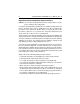
ST43401N/ND, ST43402ND User’s Manual, Rev. B iii Preface This manual contains information for users of Seagate® ST43401N/ND and ST43402ND Elite™ disc drives. It provides instructions to all personnel who operate the drive and to customer engineers who install and check out the drive. Additional information is available in the reference manual (publication 83327730). Electrostatic discharge protection Caution.
iv ST43401N/ND, ST43402ND User’s Manual, Rev. B Important safety information and precautions Caution. Use forced-air ventilation when bench-testing the drive to ensure proper cooling of drive components. Use proper safety and repair techniques for safe, reliable operation of this unit. Service should be done only by qualified persons. We recommend the procedures in this manual as effective ways of servicing the unit. Some procedures require the use of special tools.
ST43401N/ND and ST43402ND User’s Manual, Rev. B v • Do not remove any circuit boards from the drive chassis. Return the entire drive for depot repair if any circuit board is defective. Removal of circuit boards by personnel not performing depot repair will damage components and may void the warranty. • Do not remove the head and disc assembly (HDA) from the drive chassis. Return the entire drive for depot repair if the HDA is defective. • Do not attempt to disassemble the HDA. It is not field repairable.
vi ST43401N/ND, ST43402ND User’s Manual, Rev. B Wichtige Sicherheitshinweise Vorsicht. Beim Testen des Laufwerks auf dem Prüftisch ist Fremdbelüftung vorzusehen, um eine ausreichende Kühlung der Laufwerkkomponenten sicherzustellen. Verwenden Sie geeignete Sicherheits- und Reparaturverfahren, um den sicheren, zuverlässigen Betrieb dieser Einheit zu gewährleisten. Reparaturen dürfen nur von qualifiziertem Fachpersonal vorgenommen werden.
ST43401N/ND, ST43402ND User’s Manual, Rev. B vii • Tragen Sie Sicherheitsschuhe, wenn Sie schwere Teile aus- bzw. einbauen. • Wenn das Laufwerk in einem Einbaugestell oder Gehäuse montiert ist, sorgen Sie dafür, daß die Temperatur im Inneren des Gestells oder Gehäuses die für das Laufwerk vorgegebenen Grenzwerte nicht übersteigt. Wenn Einheiten vertikal gestapelt werden, achten Sie besonders auf den oberen Stapelbereich, da dort die Temperatur gewöhnlich am höchsten ist.
viii ST43401N/ND, ST43402ND User’s Manual, Rev. B Dieses Gerät ist eine Baugruppe und unterliegt als solche nicht den Anforderungen der FCC oder ähnlicher nationaler Behörden für eigenständige. Technische Testergebnisse zu Frequenz- und Elektrizitätsemissionen sind für Designer von Untersystemen auf Anfrage von der SeagateSicherheitsabteilung erhältlich.
ST43401N/ND, ST43402ND User’s Manual, Rev. B ix Technical support services Seagate Technology provides technical support literature and diagnostic utilities to authorized distributors. Please contact your dealer for technical support and installation troubleshooting. Product technical support is available for all Seagate products by calling the SeaFAX™, SeaFONE™, SeaTDD™, or SeaBOARD™ services. These are toll calls if you dial from outside of the number’s local dialing area.
x ST43401N/ND, ST43402ND User’s Manual, Rev.
ST43401N/ND, ST43402ND User’s Manual, Rev. B 1 Section 1. General description Seagate ST43401N/ND and ST43402ND Elite 3 disc drives are high speed, random access digital data storage devices. They communicate with an initiator using the fast and wide (16-bit) Small Computer System Interface (SCSI-2). The ST43401N/ND disc drive is shown in Figure 1, and the ST43402ND (dual port) disc drive is shown in Figure 2. Specifications for these drives are listed in Table 1 following the figures.
2 ST43401N/ND, ST43402ND User’s Manual, Rev. B Power Board Control Board Remote Operator Panel Connector Optional Bezel Spindle Sync Connector Port B I/O Connector I/O Board Power Pin 1 DC Power Connector Chassis Option Jumpers Port B Terminator Power Port A Terminator Power Head and Disc Assembly (HDA) I/O Board Figure 2.
ST43401N/ND, ST43402ND User’s Manual, Rev. B 3 Table 1.
4 ST43401N/ND, ST43402ND User’s Manual, Rev. B continued from previous page Characteristics SCSI transfer rate, burst Conditions Specifications 20.0 Mbytes/sec max Seek time (time required to move heads to a different track address—excluding SCSI I/O overhead) Typical full Typical average Typical one-track 23.5 msec 11.5 msec 1.7 msec Single track seek Average seek Maximum seek Write msec 1.7 11.5 23.
ST43401N/ND, ST43402ND User’s Manual, Rev. B 5 The drive contains all the circuits and mechanical devices necessary to record data on and recover it from its discs. The drive requires DC voltage inputs from an external power supply, which you must supply. The DC power cable is available as an accessory. The ST43401N/ND drives consist of a head and disc assembly (HDA) with two circuit boards, and the ST43402ND drive consists of an HDA and three circuit boards.
6 ST43401N/ND, ST43402ND User’s Manual, Rev. B When the drive is not powered on, the heads rest on the disc surface in a preassigned landing zone beyond the data zone. The actuator automatically latches in this position at shutdown for moving or shipping protection. When the drive is activated to bring the discs up to speed, the heads fly on a cushion of air close to the disc surface.
ST43401N/ND, ST43402ND User’s Manual, Rev. B 7 Section 2. Installation/Abschnitt 2. Installation The information contained in this section describes installation and initial checkout of the drive. Site requirements The site requirements considered are environment, airflow, space, power, grounding, and interface. Voraussetzungen am Aufstellungsort Zu den Voraussetzungen am Aufstellungsort gehören Umgebung, Luftfluß, Raum, Strombedingungen, Erdung und Schnittstelle.
8 ST43401N/ND, ST43402ND User’s Manual, Rev. B Table 2.
ST43401N/ND, ST43402ND User’s Manual, Rev. B Tabelle 2. Umgebungsbedingungen des Laufwerkes Bedingungen Technische Daten Betriebsumgebung Temperatur 5°C bis 50°C mit einer maximalen Schwankung von 20°C pro Stunde Relative Luftfeuchtigkeit 5% bis 95% Maximale Naßthermometertemperatur von 26°C Luftdruck – 305 m bis 3.
10 ST43401N/ND, ST43402ND User’s Manual, Rev. B Air-flow requirements The enclosure design must ensure adequate cooling for the drive. Note that the fan in the power supply cools only the power supply’s internal parts. The drive’s product specification (document 64403603) describes how to evaluate the air-flow design. The evaluation consists of ensuring that the case temperatures of certain critical components remain within acceptable limits during drive operation.
ST43401N/ND, ST43402ND User’s Manual, Rev. B 11 Above unit Under unit Note. Air flows in the direction shown (front to back) or in reverse direction (back to front) Above unit Note. Air flows in the direction shown or in reverse direction (side to side) Under unit Figure 4.
12 ST43401N/ND, ST43402ND User’s Manual, Rev. B Space requirements The drive is designed to be mounted in one of the three orientations shown in Figure 5. The drive may be mounted on its base or on either side. The physical dimensions of the drive are shown in Figure 6. The drive weighs 3.6 kg (8.0 lb). For details about designing an enclosure to match the drive mounting dimensions, refer to the drive’s product specification.
ST43401N/ND, ST43402ND User’s Manual, Rev. B 13 Up Up Up Figure 5.
14 ST43401N/ND, ST43402ND User’s Manual, Rev. B 82.55 mm 3.25 in 149.35 mm 5.88 in Figure 6. Dimensions of the drive/ Laufwerkabmessungen 203.20 mm 8.
ST43401N/ND, ST43402ND User’s Manual, Rev. B 15 Power requirements The voltage and current requirements for a single drive at cylinder 0 are shown in Table 3. Ensure that your power supply meets these requirements. Table 3. Single drive voltage and current requirements Voltage Current without Internal Terminator Seeking Continand uous Idle Reading Reading SCSI single-ended interface (ST43401N) +5V 1.8A 1.9A 1.9A +12V 1.8A 1.8A 1.8A Watts 30.6W 31.1W 31.1W SCSI differential interface (ST43401ND) +5V 1.
16 ST43401N/ND, ST43402ND User’s Manual, Rev. B continued from previous page Maximum Current Limits Regulation ± 5%3,4,8,9 SCSI single-ended interface (ST43401N) Maximum operating current1,2,6 Average idle current1 Maximum starting current1,2 Maximum seek current2 Without Internal Terminator +5V5,7 +12V5,7 Amps 1.9 1.8 1.9 1.9 1.8 1.8 4.5 3.2 SCSI differential interface (ST43401ND) Maximum operating current1,2,6 Average idle current1 Maximum starting current1,2 Maximum seek current9 1.9 1.8 1.9 1.
ST43401N/ND, ST43402ND User’s Manual, Rev. B 17 Grounding requirements A safety ground must be provided by the site AC power system. The green wire (or green wire with yellow stripe) in the AC power cord provides the safety ground connection between the power supply and the site AC power system. The site AC power system must provide the safety ground to earth ground connection.
18 ST43401N/ND, ST43402ND User’s Manual, Rev. B A connector (J6) at the back of the drive accepts the I/O cable that connects it to the system. The daisy-chain cable is a continuous unshielded cable having one connector for each drive it connects to. Refer to the reference manual (publication 83327730) for guidelines on I/O cabling. These guidelines discuss the use of unshielded cabling inside cabinets and shielded cabling running between cabinets.
ST43401N/ND, ST43402ND User’s Manual, Rev. B 19 Table 4.
20 ST43401N/ND, ST43402ND User’s Manual, Rev. B Table 5.
ST43401N/ND, ST43402ND User’s Manual, Rev. B 21 continued from previous page Signal name GROUND DB– (8) DB– (9) DB– (10) DB– (11) Even pin numbers 60 62 64 66 68 Signal name GROUND DB (8) DB (9) DB (10) DB (11) Odd pin numbers 59 61 63 65 67 Notes: 1. A minus sign indicates active low. 2.
22 ST43401N/ND, ST43402ND User’s Manual, Rev. B Unpacking, inspection, and repacking After removing the packing material, inspect the drive for shipping damage. Save all packing materials for future use. The drive is shipped separately from any other items ordered for the installation. Unpacking 1. Allow the drive temperature to approach the ambient temperature of the unpacking area. Ensure that the temperature stabilization period meets the requirements printed on the drive container. 2.
ST43401N/ND, ST43402ND User’s Manual, Rev. B 23 Installation procedures With the site requirements completed, the enclosure designed, and the drive unpacked you are ready to begin the installation. The following procedures are included in drive installation: • • • • • • • Setting the circuit board jumpers Installing a power supply Attaching an optional bezel Mounting the drive Connecting the system I/O cabling Grounding the system Synchronizing the spindle Setting the control board jumpers Caution.
24 ST43401N/ND, ST43402ND User’s Manual, Rev.
ST43401N/ND, ST43402ND User’s Manual, Rev.
26 ST43401N/ND, ST43402ND User’s Manual, Rev.
ST43401N/ND, ST43402ND User’s Manual, Rev.
28 ST43401N/ND, ST43402ND User’s Manual, Rev. B J01B = Jumper connected Port B I/O = Jumper not connected = Non-applicable jumper (not relevant to the option discussed) J01A J03 Port A I/O Enable/Disable Port A (EPA) Ground (GND) Enable/Disable Port B (EPB) Ground (GND) Enable/Disable Port A EPA GND EPB GND J01 (A & B) 4 2 Enable Port A Disable Port A Enable/Disable Port B Enable Port B Terminator Power J01A is for Port A and J01B is for Port B.
ST43401N/ND, ST43402ND User’s Manual, Rev. B 29 Installing a power supply A power supply is required to provide current to the disc drive. Several vendors offer power supplies that meet the disc drive’s power requirements. Ensure that the power supply you select meets these requirements as specified in Table 3. Setting the voltage range Caution. Most power supplies will be damaged if the voltage select is set for the low range (100–120 VAC) and a voltage in the high range (208– 240 VAC) is applied. 1.
30 ST43401N/ND, ST43402ND User’s Manual, Rev. B Attaching an optional bezel Use the following procedure to attach an optional bezel to the drive. The bezel is available as an accessory (see Section 4). 1. Remove the backing from the double-sticky tape attached to the rear surface of the bezel. 2. Orient the drive and bezel as shown in Figure 13. 3. Align the mounting bosses on the rear of the bezel to the matching holes in the drive chassis. 4.
ST43401N/ND, ST43402ND User’s Manual, Rev. B 31 Mounting the drive Caution. When installing the drive, observe all precautions listed under “Electrostatic discharge protection” in the preface. Failure to observe these precautions can result in serious damage to electronic assemblies. The drive may be secured to the enclosure using the tapped holes in either the sides or the bottom of the drive chassis. Figure 14 shows two of the three allowable orientations. Note.
32 ST43401N/ND, ST43402ND User’s Manual, Rev. B 1 6-32 Bottom-Mounting Screws (4) 2 DC power and pin connector assignments 1 2 3 4 Drive Power Pin 1 +12 VDC 2 +12 Volts return 3 +5 Volts return 4 +5 VDC Up Power Supply (9 pin) Pin Number 7, 8 6, 9 3, 4 1, 2 Up 2 DC Power Connector J15 Pin 1 DC Power Cable M4 x .70 (metric) M4 x .70 (metric) Note: 1 Either side- or bottom-mounting screws can be used with each drive orientation Figure 14.
ST43401N/ND, ST43402ND User’s Manual, Rev. B 33 Connecting the system I/O cabling Make sure the site has been prepared in accordance with the site requirements information provided earlier in this section. This procedure describes how to cable the system in a daisy-chain configuration, which was discussed earlier in this section in “Interface requirements.” ST43401N/ND drives The drive has one I/O connector on the control board. Figure 15 shows how a typical I/O cable connects to the board.
34 ST43401N/ND, ST43402ND User’s Manual, Rev. B ST43402ND drives ST43402ND drives have two I/O connectors as shown in Figure 16. Both of these I/O connectors (one for Port A and the other for Port B) are located on the I/O board. Figure 16 shows how typical I/O cables connect to the I/O board. You must use an adapter (part number 70935801) to terminate each I/O cable following the last drive in the daisy chain.
ST43401N/ND, ST43402ND User’s Manual, Rev. B 35 Figure 17 shows how the terminator resistor-paks are attached on ST43401N drives (single-ended I/O). The terminator resistor-paks, which are single inline packages, mount in the rows of holes located in the control board. Ensure that they are installed with the correct orientation (indicated by a dot above pin 1) to terminate these drives.
36 ST43401N/ND, ST43402ND User’s Manual, Rev. B Figure 18 shows how the terminator resistor-paks are attached on ST43401ND drives (differential I/O). These terminator resistor-paks, which are dual inline packages, mount in sockets in the control board. These terminators are also marked with a dot above pin 1. If the drive is located at either end of the daisy chain, ensure that it has resistor-pak(s) installed. Refer to information earlier in this section regarding the terminator power source jumper.
ST43401N/ND, ST43402ND User’s Manual, Rev. B 37 Grounding the system Grounding the system through the power cables and I/O cables is usually sufficient to protect against noise and emissions. Synchronizing the spindle The spindle sync feature makes it possible to synchronize the spindle rotation of a group of disc drives. This reduces the latency normally encountered when the initiator switches between multiple disc drives. Figure 19 shows two system configurations.
38 ST43401N/ND, ST43402ND User’s Manual, Rev. B To enable the feature, it is necessary to run an additional daisy-chain cable from drive to drive and to make a master/slave selection for each drive. Connector J7 is used by ST43401N/ND drives. Connector J5 on the control board handles the cable connections on ST43402ND drives. Master/slave selection is made by a jumper on connector J4A. Figure 20 shows the two connectors for ST43401N/ND drives, and Figure 21 shows the two connectors for ST43402ND drives.
ST43401N/ND, ST43402ND User’s Manual, Rev. B J5 39 Pin 1 Cable from Preceding Unit A B Cable to Next Unit Control Board J4A Select Plug (removed = master) Slave Select Figure 21.
40 ST43401N/ND, ST43402ND User’s Manual, Rev. B For each drive in the middle of the daisy chain, the cable from the preceding unit connects to one row of pins in (row A or row B), and the cable to the next unit connects to the other row of pins. There are two ways to establish a drive as a master (supplying the sync reference signal to all drives connected for spindle sync). • Remove the jumper connecting the master/slave pins on connector J4A (the drives are shipped with the pins disconnected).
ST43401N/ND, ST43402ND User’s Manual, Rev. B 41 Verification After installing the drive, follow the sequence outlined below for initial startup. 1. Place the on/standby switch in the on ( l ) position. What follows depends on the setting of the Start Command option and the Spinup Delay option jumpers. • If the Start Command option jumper was connected, the spindle spinup begins immediately after a Start Unit command is received from the SCSI bus.
ST43401N/ND, ST43402ND User’s Manual, Rev. B 43 Section 3. Operation This section provides the information and instructions to operate the drive. It is arranged as follows: • LED indicators—locates and describes the switches and indicators used for normal drive operation. • Operating instructions—describes procedures for operating the drive. LED indicators Following initial checkout, the drive normally requires no attention from the operator.
44 ST43401N/ND, ST43402ND User’s Manual, Rev. B Socket for Active LED (red) Heartbeat LED (green) Ready LED (green) Control Board Figure 22.
ST43401N/ND, ST43402ND User’s Manual, Rev. B 45 Table 6. LED functions for ST43401N/ND drives LED indicator Drive control board Ready LED (green) Function This LED flashes during the power-on sequence until the discs are up to speed and the heads are loaded. It is on steady with power-on complete, assuming that there are no fault conditions. It flashes during a power-off sequence. This occurs when the drive receives a Start/Stop Unit command after it has once been started.
46 ST43401N/ND, ST43402ND User’s Manual, Rev. B Socket for Active LED (red) Heartbeat LED (green) Ready LED (green) Control Board Port A Enabled LED (green) Port B Active LED (red) Port B Enabled LED (green) Figure 23.
ST43401N/ND, ST43402ND User’s Manual, Rev. B 47 Table 7. LED functions for ST43402ND drives LED indicator Drive control board Ready LED (green) Function This LED flashes during the power-on sequence until the discs are up to speed and the heads are loaded. It is on steady with power-on complete, assuming that there are no fault conditions. It flashes during a power-off sequence. This occurs when the drive receives a Start/Stop Unit command after it has once been started.
48 ST43401N/ND, ST43402ND User’s Manual, Rev. B continued from previous page LED or indicator SCSI I/O board SCSI port A enabled (green) Function This LED is on steady when port A is enabled to receive SCSI commands and to transfer data on this port. SCSI port B enabled (green) This LED is on steady when port B is enabled to receive SCSI commands and to transfer data on this port. SCSI port A active (red) This LED is on when port B is actively executing a SCSI command.
ST43401N/ND, ST43402ND User’s Manual, Rev. B 49 Section 4. Parts data This section lists part numbers of options and accessories that can be used in a drive installation. Because the drive is depot repairable, there are no fieldreplaceable parts. If the drive requires maintenance, refer to the instructions in Section 5. Table 8 lists the part numbers for options and accessories for system installation.
50 ST43401N/ND, ST43402ND User’s Manual, Rev. B Table 8.
ST43401N/ND, ST43402ND User’s Manual, Rev. B 51 Section 5. Maintenance This section contains the following maintenance information: • • • • Observing maintenance precautions Arranging for depot repair Removing and replacing a drive Packing a drive for shipment Observing maintenance precautions Because the drive is depot repairable, there are no field-replaceable parts.
52 ST43401N/ND, ST43402ND User’s Manual, Rev. B Arranging for depot repair Before returning any units to Seagate, it is necessary to obtain a returned material authorization (RMA) number. To get the number, you will need to know the part number and serial number of the unit. These numbers appear on a label located on the side of the HDA. Then contact: Seagate Technology, Inc. Customer Services Phone: 1-800-468-3472 Removing and replacing a drive Caution.
Seagate Technology, Inc. 920 Disc Drive, Scotts Valley, CA 95066-4544, USA Publication Number: 83327720, Rev.