Product Manual Seagate® 600 Pro SSD Standard 2.5” Managed Life models Standard 2.5” Usage Based models ST480FP0001 ST400FP0001 ST240FP0001 ST200FP0001 ST120FP0001 ST100FP0001 ST480FP0021 ST400FP0021 ST240FP0021 ST200FP0021 ST120FP0021 ST100FP0021 100727924 Rev.
Document Revision History Revision Date Description of changes Rev. A 05/10/2013 Initial release. © 2013 Seagate Technology LLC. All rights reserved. Publication number: 100727924, Rev. A May 2013 Seagate, Seagate Technology and the Wave logo are registered trademarks of Seagate Technology LLC in the United States and/or other countries.
Contents Seagate® Technology Support Services . . . . . . . . . . . . . . . . . . . . . . . . . . . . . . . . . . . . . . . . . . . . . . . . . 1 1.0 Introduction. . . . . . . . . . . . . . . . . . . . . . . . . . . . . . . . . . . . . . . . . . . . . . . . . . . . . . . . . . . . . . . . . . . 2 1.1 About the Serial ATA interface . . . . . . . . . . . . . . . . . . . . . . . . . . . . . . . . . . . . . . . . . . . . . . 2 2.0 Drive specifications . . . . . . . . . . . . . . . . . . . . . . . . . . . .
FIGURES Figure 1. Figure 2. Figure 3. Figure 4. Typical 5V Startup and Operation Current Profile . . . . . . . . . . . . . . . . . . . . . . . . . . . . . . . . . . 13 Attaching SATA cabling . . . . . . . . . . . . . . . . . . . . . . . . . . . . . . . . . . . . . . . . . . . . . . . . . . . . . . 19 Mounting configuration dimensions (7mm models) . . . . . . . . . . . . . . . . . . . . . . . . . . . . . . . . . 20 Air flow . . . . . . . . . . . . . . . . . . . . . . . . . . . . . . . . . . . . . . . . . .
Seagate® Technology Support Services For information regarding online support and services, visit http://www.seagate.com/about/contact-us/technical-support/ Available services include: • Presales & Technical support • Global Support Services telephone numbers & business hours • Authorized Service Centers Warranty terms will vary based on type of warranty chosen: “Managed Life” or “Usage Based”. Consult your Seagate sales representative for warranty terms and conditions.
1.0 INTRODUCTION This manual describes the functional, mechanical and interface specifications for the following Seagate® 600 Pro SSD model drives: 2.5" MANAGED LIFE MODEL 2.5" USAGE BASED MODEL ST480FP0001 ST480FP0021 ST400FP0001 ST400FP0021 ST240FP0001 ST240FP0021 ST200FP0001 ST200FP0021 ST120FP0001 ST120FP0021 ST100FP0001 ST100FP0021 These drives provide the following key features: • Multi-Level Cell (MLC) NAND Flash storage. • Serial ATA 3.1 Host Interface (SATA 6Gb/s).
2.0 DRIVE SPECIFICATIONS Unless otherwise noted, all specifications are measured under ambient conditions, at 25°C, and nominal power. For convenience, the phrases the drive and this drive are used throughout this manual to indicate the following drive models: Capacity 480GB 400Gb 240GB 200GB 120GB 100GB 2.5” Managed Life Warranty ST480FP0001 ST400FP0001 ST240FP0001 ST200FP0001 ST120FP0001 ST100FP0001 2.
ST480FP0001 ST480FP0021 Drive specification ST400FP0001 ST400FP0021 ST240FP0001 ST240FP0021 ST200FP0001 ST200FP0021 Altitude, operating –61 m to 3048 m (–200 ft. to 10,000+ ft.) Altitude, nonoperating (below mean sea level, max) –61 m to 12,192 m (–200 ft to 40,000+ ft) Operational Shock (max at 0.5ms) ST100FP0001 ST100FP0021 1000 Gs Non-Operational Shock (max at 0.5ms) 1000 Gs Vibration, random operating 20–2000 Hz: 11.08 Grms Vibration, random nonoperating 20–2000 Hz: 11.
2.4 PERFORMANCE, RECORDING AND INTERFACE TECHNOLOGY 2.4.1 Interface technology 480GB 400GB 240GB 200GB 120GB 100GB MODELS MODELS MODELS MODELS MODELS MODELS Interface Serial ATA (SATA-II) Interface Speeds Supported 6Gb/s, 3Gb/s, 1.5Gb/s Maximum Burst Transfer Rate 600MB/s Hot Plug Support Yes Native Command Queuing Support Yes Trim Support Yes Lifetime Endurance Management Option Yes 2.4.
When evaluating performance of SSD devices, it is recommended to measure performance of the device in a method that resembles the targeted application using real world data and workloads. Test time should also be adequately large to ensure that sustainable metrics and measures are obtained. 2.5 PHYSICAL CHARACTERISTICS 2.5” models Maximum height 7.00 mm (0.276 in) Maximum width 70.10 mm (2.760 in) Maximum length 100.45 mm (3.955 in) Max weight 100 g (0.220 lb) 2.
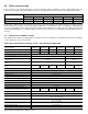
2.8 POWER SPECIFICATIONS The drive receives DC power (+5V) through a native SATA power connector. See Figure 2 on page 19. 2.8.1 Power consumption Power requirements for the drives are listed in the table on page 9. Typical power measurements are based on an average of drives tested, under nominal conditions, at 35°C ambient temperature. • Startup power Startup power is measured from the time of power-on to the time that the drive reaches operating condition and can process media access commands.
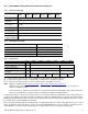
Table 3 400GB DC power requirements Parameter Voltage Regulation ST400FP00x1 (6.0Gb) +5V Power +/- 5% (watts) Average Idle Current 0.45 2.27 Average Sleep Current 0.10 0.52 DC (Peak DC) 0.58 2.89 AC (Peak AC) 0.98 4.90 Delayed Motor Start (DC max) 0.10 0.49 Typical DC 0.37 1.86 Maximum DC 0.38 1.90 Maximum DC (peak) 1.02 5.10 Typical DC 0.40 2.00 Maximum DC 0.43 2.14 Maximum DC (peak) 1.48 7.40 Typical DC 0.47 2.37 Maximum DC 0.48 2.41 Maximum DC (peak) 1.06 5.
Table 4 240GB DC power requirements Parameter Voltage Regulation ST240FP00x1 (6.0Gb) +5V Power +/- 5% (watts) Average Idle Current 0.47 2.37 Average Sleep Current 0.10 0.49 DC (Peak DC) 0.56 2.78 AC (Peak AC) 0.90 4.50 Delayed Motor Start (DC max) 0.10 0.48 Typical DC 0.35 1.75 Maximum DC 0.37 1.83 Maximum DC (peak) 1.00 5.00 Typical DC 0.41 2.06 Maximum DC 0.46 2.31 Maximum DC (peak) 1.26 6.30 Typical DC 0.44 2.20 Maximum DC 0.45 2.24 Maximum DC (peak) 0.92 4.
Table 5 200GB DC power requirements Parameter Voltage Regulation ST200FP00x1 (6.0Gb) +5V Power +/- 5% (watts) Average Idle Current 0.45 2.25 Average Sleep Current 0.09 0.47 DC (Peak DC) 0.56 2.80 AC (Peak AC) 0.88 4.40 Delayed Motor Start (DC max) 0.10 0.48 Typical DC 0.34 1.71 Maximum DC 0.36 1.80 Maximum DC (peak) 0.96 4.80 Typical DC 0.38 1.92 Maximum DC 0.42 2.11 Maximum DC (peak) 1.20 6.00 Typical DC 0.45 2.26 Maximum DC 0.46 2.28 Maximum DC (peak) 0.92 4.
Table 6 120GB DC power requirements Parameter Voltage Regulation ST120FP00x1 (6.0Gb) +5V Power +/- 5% (watts) Average Idle Current 0.45 2.24 Average Sleep Current 0.09 0.46 DC (Peak DC) 0.53 2.66 AC (Peak AC) 0.96 4.78 Delayed Motor Start (DC max) 0.10 0.48 Typical DC 0.35 1.74 Maximum DC 0.36 1.81 Maximum DC (peak) 0.92 4.60 Typical DC 0.49 2.43 Maximum DC 0.50 2.52 Maximum DC (peak) 1.12 5.60 Typical DC 0.50 2.48 Maximum DC 0.51 2.54 Maximum DC (peak) 1.02 5.
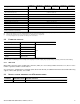
Table 7 100GB DC power requirements Parameter Voltage Regulation ST100FP00x1 (6.0Gb) +5V Power +/- 5% (watts) Average Idle Current 0.42 2.10 Average Sleep Current 0.09 0.46 DC (Peak DC) 0.54 2.68 AC (Peak AC) 0.89 4.46 Delayed Motor Start (DC max) 0.10 0.48 Typical DC 0.36 1.79 Maximum DC 0.36 1.80 Maximum DC (peak) 0.92 4.60 Typical DC 0.42 2.12 Maximum DC 0.43 2.17 Maximum DC (peak) 1.08 5.40 Typical DC 0.48 2.39 Maximum DC 0.48 2.42 Maximum DC (peak) 0.94 4.
2.8.2.1 Figure 1. Typical current profiles Typical 5V Startup and Operation Current Profile SEAGATE 600 PRO SSD PRODUCT MANUAL, REV.
2.9 ENVIRONMENTAL SPECIFICATIONS 2.9.1 Temperature Temperature is defined as the drive's internal temperature as reported by SMART attribute 194 for operation or the drive case temperature for non-operating. Above 1000 feet (305 meters), the maximum temperature is derated linearly to 112°F (44°C) at 10,000 feet (3048 meters). Operating: 0° to 70°C (32° to 158°F) Nonoperating: –40° to 75°C (–40° to 167°F) 2.9.
2.9.6.1 Operating vibration The maximum random vibration levels that the drive may experience while meeting the performance standards specified in this document are specified below. This specification does not cover connection issues that may result from testing at this level. 20–2000 Hz 2.9.6.2 11.
2.11 RELIABILITY 2.11.1 Annualized Failure Rate (AFR) and Mean Time Between Failures (MTBF) The product shall achieve an Annualized Failure Rate - AFR - of 0.58%. AFR and MTBF are population statistics that are not relevant to individual units. AFR and MTBF specifications are based on the following assumptions: • • • • 8760 power-on-hours per year. 250 average power cycles per year. Operations at nominal voltages.
2.12 AGENCY CERTIFICATION 2.12.1 Safety certification These products are certified to meet the requirements of UL60950-1, CSA60950-1 and EN60950 and so marked as to the certify agency. 2.12.2 Electromagnetic compatibility Drives that display the CE mark comply with the European Union (EU) requirements specified in the Electromagnetic Compatibility Directive (2004/108/EC) as put into place 20 July 2007.
2.13 ENVIRONMENTAL PROTECTION Seagate designs its products to meet environmental protection requirements worldwide, including regulations restricting certain chemical substances. 2.13.1 European Union Restriction of Hazardous Substances (RoHS) Directive The European Union Restriction of Hazardous Substances (RoHS) Directive, restricts the presence of chemical substances, including Lead, Cadmium, Mercury, Hexavalent Chromium, PBB and PBDE, in electronic products, effective July 2006.
3.0 CONFIGURING AND MOUNTING THE DRIVE This section contains the specifications and instructions for configuring and mounting the drive. 3.1 HANDLING AND STATIC-DISCHARGE PRECAUTIONS After unpacking, and before installation, the drive may be exposed to potential handling and electrostatic discharge (ESD) hazards.
3.4 DRIVE MOUNTING You can mount the drive in any orientation using four screws in the side-mounting holes or four screws in the bottommounting holes. Follow these important mounting precautions when mounting the drive: • Allow a minimum clearance of 0.030 in (0.76 mm) around the entire perimeter of the drive for cooling as a guideline. Please refer to Section 3.5 for final cooling requirements. • Use only M3 x 0.5 metric mounting screws. • Four (4) threads (0.080 in) minimum screw engagement recommended.
3.5 COOLING Cabinet cooling must be designed by the customer so that the ambient temperature immediately surrounding the drive will not exceed temperature conditions specified in Section 2.9.1, "Temperature." The rack, cabinet, or drawer environment for the drive must provide heat removal. You should confirm that adequate heat removal is provided using the temperature measurement guidelines described in Section 2.9.1.
4.0 SERIAL ATA (SATA) INTERFACE These drives use the industry-standard Serial ATA interface that supports FIS data transfers. It supports ATA programmed input/output (PIO) modes 0–4; multiword DMA modes 0–2, and Ultra DMA modes 0–6. For detailed information about the Serial ATA interface, refer to the “Serial ATA: High Speed Serialized AT Attachment” specification. 4.
Table 10 summarizes the 1.8” drive Signal and Power SATA Plug. Table 10 1.
4.3 SUPPORTED ATA COMMANDS The following table lists Serial ATA standard commands that the drive supports. For a detailed description of the ATA commands, refer to the Serial ATA: High Speed Serialized AT Attachment specification. See “S.M.A.R.T. commands” on page 33 for details and subcommands used in the S.M.A.R.T. implementation.
COMMAND NAME COMMAND CODE (IN HEX) Set Multiple Mode C6H Sleep E6H S.M.A.R.T. Disable Operations B0H / D9H S.M.A.R.T. Enable Operations B0H / D8H S.M.A.R.T. Execute Offline B0H / D4H S.M.A.R.T. Read Data B0H / D0H S.M.A.R.T. Read Log Sector B0H / D5H S.M.A.R.T. Return Status B0H / DAH S.M.A.R.T.
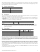
4.3.1 Identify Device command The Identify Device command (command code ECH) transfers information about the drive to the host following power up. The data is organized as a single 512-byte block of data, whose contents are shown in Table 11 on page 24. All reserved bits or words should be set to zero. Parameters listed with an “x” are drive-specific or vary with the state of the drive. see Section 2.0 on page 3 for default parameter settings.
WORD DESCRIPTION VALUE 67 Minimum PIO transfer cycle time without flow control (120ns) 0078H 68 Minimum PIO transfer cycle time with IORDY flow control (120ns) 0078H 69 Additional Features and Commands supported.
WORD DESCRIPTION VALUE 120 Commands and feature sets supported or enabled 401CH 121–126 Reserved for expanded supported and enabled settings 0000H 127 Obsolete 0000H 128 Security status 0021H 129–159 Vendor specific xxxxH 160–167 Reserved for the CompactFlash Association 0000H 168 Device Nominal Form Factor 0003H 169 DATA SET MANAGEMENT features supported 0001H 170–173 Additional Product Identifier (ATA String) 0000H 174–175 Reserved 0000H 176–205 Reserved 0000H 206 SCT
Bit Word 69 5 Read zero after Trim is supported 6 Optional ATA 28-bit commands supported 8 Download Microcode DMA supported 9 Set Max Password DMA and Set Max Unlock DMA supported 10 Write Buffer DMA Supported 11 Read Buffer DMA Supported 12 DEVICE CONFIGURATION IDENTIFY DMA and DEVICE CONFIGURATION SET DMA are supported 13 Long Physical Sector Alignment Error Reporting Control is supported 14 Deterministic read after Trim is supported Bit Word 76 0 Shall be cleared to zero 1 Suppor
Bit Word 83 0 DOWNLOAD MICROCODE command is supported 1 Obsolete 2 CFA feature set is supported 3 APM feature set is supported 4 Obsolete 5 PUIS feature set is supported 6 SET FEATURES subcommand is required to spin-up after power-up 7 Reserved 8 SET MAX security extension is supported 9 AAM feature set is supported 10 48-bit Address feature set is supported 11 DCO feature set is supported 12 Mandatory FLUSH CACHE command is supported 13 FLUSH CACHE EXT command is supported 14
Bit Word 87 0 SMART error logging is supported 1 SMART self-test supported 3 The Media Card Pass Through Command feature set is supported 5 The GPL feature set is supported 6 WRITE DMA FUA EXT and WRITE MULTIPLE FUA EXT commands are supported 8 The 64-bit World wide name is supported 13 The IDLE IMMEDIATE command with UNLOAD FEATURE is supported 14 Shall be set to one 15 Shall be cleared to zero Bit Word 119 0 Reserved 1 Write-Read-Verify feature set is supported 2 WRITE UNCORRECT
4.3.2 Set Features command This command controls the implementation of various features that the drive supports. When the drive receives this command, it sets BSY, checks the contents of the Features register, clears BSY and generates an interrupt. If the value in the register does not represent a feature that the drive supports, the command is aborted. Power-on default has the read look-ahead and write caching features enabled.
4.3.3 S.M.A.R.T. commands S.M.A.R.T. provides near-term failure prediction for drives. When S.M.A.R.T. is enabled, the drive monitors predetermined drive attributes that are susceptible to degradation over time. If self-monitoring determines that a failure is likely, S.M.A.R.T. makes a status report available to the host. Not all failures are predictable. S.M.A.R.T. predictability is limited to the attributes the drive can monitor. For more information on S.M.A.R.T.
INDEX A European Union (EU) requirements 17 ACA 17 acceleration 15 Access time 6 Agency certification 17 air flow illustrated 21 altitude 14 ambient temperature 6, 7 Annualized Failure Rate (AFR) 16 ATA commands 24 Australia/New Zealand Standard AS/NZ CISPR22 17 Australian Communication Authority (ACA) 17 Australian C-Tick 17 Average seek time 6 F C cables and connectors 19 capacity 4 CE mark 17 certification 17 Check Power Mode 24 China RoHS directive 18 Class B computing device 17 compatibility 17 Con
INDEX mounting the drive 19 N nominal power 6 Nonoperating shock 14 Nonoperating vibration 15 NOP 24 O Operating shock 14 Operating vibration 15 P Page-to-page access 6 page-to-page accesses 6 Peak operating mode 7 Performance 5 Physical characteristics 6 point-to-point 2, 19 Power consumption 7 Power specifications 7 precautions 19 printed circuit board 19 Q quick reference 3 R Radiated RF immunity 15 Radio and television interference 17 radio frequency (RF) 15 Read Buffer 24 Read DMA 24 Read DMA Exte
INDEX width 6 Write Buffer 25 Write DMA 25 Write DMA Extended 25 Write DMA FUA Extended 25 Write FPDMA queued 25 Write Log Extended 25 Write Multiple 25 Write Multiple Extended 25 Write Multiple FUA Extended 25 Write Sectors 25 Write Sectors Extended 25 write uncorrectable 25 SEAGATE 600 PRO SSD PRODUCT MANUAL, REV.
Seagate Technology LLC AMERICAS Seagate Technology LLC 10200 South De Anza Boulevard, Cupertino, California 95014, United States, 408-658-1000 ASIA/PACIFIC Seagate Singapore International Headquarters Pte. Ltd. 7000 Ang Mo Kio Avenue 5, Singapore 569877, 65-6485-3888 EUROPE, MIDDLE EAST AND AFRICA Seagate Technology SAS 16-18 rue du Dôme, 92100 Boulogne-Billancourt, France, 33 1-4186 10 00 Publication Number: 100727924, Rev.