SATA 2.5" Product Manual Standard models ST5000LM000 ST4000LM024 ST3000LM024 100804767, Rev.
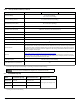
Document Revision History Revision Date Rev. A 07/19/2016 Initial release. 09/06/2016 6 & 8: Changed Weight (typical) to Weight (max) 13: Removed '2004/108/EC (Until 19th April, 2016) and' & '(From 20th April, 2016)' 13: Modified EMC Standard from EN55022 to EN55032 13: Added Korean text for Class B device warning 10/10/2016 fc: 10: 10: 13: Rev. D 11/17/2016 5: Revised bullet list 6 & 8: Revised Data transfer rate = 140MB/s 6 & 10: Start-up current = 1.2A 10: Updated Section 2.8.
Contents Seagate® Technology Support Services. . . . . . . . . . . . . . . . . . . . . . . . . . . . . . . . . . . . . . . . . . . . . . . . . . . . . . . . . . . . . . . . . . . . . . 5 1. Introduction . . . . . . . . . . . . . . . . . . . . . . . . . . . . . . . . . . . . . . . . . . . . . . . . . . . . . . . . . . . . . . . . . . . . . . . . . . . . . . . . . . . . . . . . . . . . . . . . . . . . . . . . . . . . . . . . 6 1.1 About the Serial ATA Interface . . . . . . . . . . . . . . . . . . . . . . . .
Contents 3. Unpacking, Configuring and Mounting the Drive . . . . . . . . . . . . . . . . . . . . . . . . . . . . . . . . . . . . . . . . . . . . . . . . . . . . . . . . . . . . . . . . . . . . . . . . . . . . . 20 3.1 Handling and Static-Discharge Precautions . . . . . . . . . . . . . . . . . . . . . . . . . . . . . . . . . . . . . . . . . . . . . . . . . . . . . . . . . . . . . . . . . . . . . . . . . . . . . . . . . . . . . . . . . .20 3.2 Configuring the Drive. . . . . . . . . . . . . . . . . . . . . .
Figures Figure 1. Figure 2. Attaching SATA Cabling . . . . . . . . . . . . . . . . . . . . . . . . . . . . . . . . . . . . . . . . . . . . . . . . . . . . . . . . . . . . . . . . . . . . . . . 20 Mounting Dimensions (for 1-disk models) . . . . . . . . . . . . . . . . . . . . . . . . . . . . . . . . . . . . . . . . . . . . . . . . . . . . . . 21 Seagate BarraCuda Product Manual, Rev.
Seagate® Technology Support Services For information regarding online support and services, visit: http://www.seagate.com/contacts/ For information regarding Warranty Support, visit: http://www.seagate.com/support/warranty-and-replacements/ For information regarding data recovery services, visit: http://www.seagate.com/services-software/recover/ For Seagate OEM, Distribution partner and reseller portals, visit: http://www.seagate.com/partners/ Seagate BarraCuda Product Manual, Rev.
1. Introduction This manual describes the functional, mechanical and interface specifications for the following: Seagate® BarraCuda® model drives: Standard models ST5000LM000 ST4000LM024 ST3000LM024 These drives provide the following key features: • 128MB buffer. • 5400-RPM spindle speed. • 650 Gs non-operating shock and 300 Gs of operating shock. • Full-track multiple-sector transfer capability without local processor intervention.
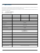
2. Specifications Unless otherwise noted, all specifications are measured under ambient conditions, at 25°C, and nominal power. For convenience, the phrases the drive and this drive are used throughout this manual to indicate the following drive models: The specification summaries listed in the following tables are for quick reference. For details on specification measurement or definition, refer to the appropriate section of this manual. 2.
Table 1 Drive Specifications Summary (continued) Drive Specification ST5000LM000 ST4000LM024 5% to 95% (operating) 5% to 95% (non-operating) Relative humidity 20°C per hour max (operating) 30°C per hour max (non-operating) Relative humidity gradient 37.7°C max (operating) 40.0°C max (non-operating) Wet bulb temperature (max) Altitude, operating –304.8 m to 3048 m (–1000 ft to 10,000+ ft) Altitude, non-operating (below mean sea level, max) –304.
2.2.1 LBA mode When addressing these drives in LBA mode, all blocks (sectors) are consecutively numbered from 0 to n–1, where n is the number of guaranteed sectors as defined above. Refer to Unpacking, Configuring and Mounting the Drive on page 20 (words 60-61 and 100-103) for additional information about 48-bit addressing support of drives with capacities over 137 GB. 2.
2.6 Seek time Seek measurements are taken with nominal power at 25°C ambient temperature. All times are measured using drive diagnostics. The specifications in the table below are defined as follows: • Average seek time is determined by averaging the time to complete 1,000 seeks of random length. • Average latency is the time required for the drive to rotate 1/2 of a revolution and on average is incurred after a seek completion prior to reading or writing user data.
2.8 Power Specifications The drive receives DC power (+5V) through a native SATA power connector (refer to1). 2.8.1 Power consumption Power requirements for the drives are listed in the table in Table 4. Typical power measurements are based on an average of drives tested, under nominal conditions, at 25°C ambient temperature. These power measurements are done with DIPM enabled. • Spinup current is measured from the time of power-on to the time that the drive spindle reaches operating speed.
2.8.4 Power-management modes The drive provides programmable power management to provide greater energy efficiency. In most systems, users can control power management through the system setup program.
2.9 Environmental Specifications This section provides the temperature, humidity, shock, and vibration specifications for Seagate BarraCuda drives. Ambient temperature is defined as the temperature of the environment immediately surrounding the drive. Above 1000 feet (305 meters), the maximum temperature is derated linearly by 1°C every 1000 feet.
2.10 Acoustics Drive emission of sound is measured consistent with the ECMA-74 and its referenced standards. Testing is conducted at room temperature (approximately 25°C). Emission levels are reported as the total A-weighted sound power levers for steady state, idle, and active seeks modes of operation. Table 6: Drive A-weighted Sound Power Levels (SWL, BA) 5TB, 4TB & 3TB models 1. Idle1 Performance Seek 2.6 bels (typ) 2.
2.12 Reliability Nonrecoverable read errors 1 per 1014 bits read, max Load/Unload (U/UL) 25°C, 50% relative humidity 600,000 software-controlled power on/off cycles 20,000 hard power on/off cycles Rated workload Average annualized workload rating: <55 TB/year. The specifications for the product assumes the I/O workload does not exceed the average annualized workload rate limit of 55 TB/year.
2.13 Agency and Safety Certifications Each Hard Drive and Solid State Drive ("drives") has a product label that includes certifications that are applicable to that specific drive. The following information provides an overview of requirements that may be applicable to the drive. 2.13.1 Safety certification The drives are recognized in accordance with UL/cUL 60950-1 and EN 60950-1. 2.13.
2.13.6 Morocco Commodity Mark To satisfy our OEM customers, Seagate has added the Moroccan Commodity Mark to the drives provided to the OEM for the sale of Customer Kits produced by our OEM customers that are intended to be incorporated into the OEM's finished system-level product by an end user. The Customer Kits are considered 'devices' under Morocco's Order of the Minister of Industry, Trade, Investment and Digital Economy No.
2.14 Environmental protection Seagate designs its products to meet environmental protection requirements worldwide, including regulations restricting certain chemical substances. 2.14.1 European Union Restriction of Hazardous Substance Law 2.14.1.1 Restriction of Hazardous Substances in Electrical and Electronic Equipment Seagate drives are designed to be compliant with the European Union RoHS "Recast" Directive 2011/65/EU (RoHS 2) as amended by Directive (EU) 2015/863.
2.14.3 Taiwan Requirements — Taiwan RoHS Taiwan RoHS refers to the Taiwan Bureau of Standards, Metrology and Inspection’s (BSMI) requirements in standard CNS 15663, Guidance to reduction of the restricted chemical substances in electrical and electronic equipment. Seagate products must comply with the “Marking of presence” requirements in Section 5 of CNS 15663, effective January 1, 2018. This product is Taiwan RoHS compliant. The following table meets the Section 5 “Marking of presence” requirements.
3. Unpacking, Configuring and Mounting the Drive This chapter describes how to unpack, mount, configure and connect a BarraCuda. It also describes how to install the drive in systems. 3.1 Handling and Static-Discharge Precautions After unpacking, and before installation, the drive may be exposed to potential handling and electrostatic discharge (ESD) hazards. Observe the following standard handling and static-discharge precautions. CAUTION 3.
3.3 Drive Mounting Users can mount the drive in any orientation using four screws in the side-mounting holes or four screws in the bottom-mounting holes. Refer to2 and Figure 2 for drive mounting dimensions. Follow these important mounting precautions when mounting the drive: • Allow a minimum clearance of 0.030 in (0.76 mm) around the entire perimeter of the drive for cooling. • Use only M3 x 0.5 mounting screws. • Do not overtighten the mounting screws. Maximum torque: 4.0 in-lb (0.4519 N-m).
4. Serial ATA (SATA) Interface These drives use the industry-standard Serial ATA interface that supports FIS data transfers. It supports ATA programmed input/output (PIO) modes 0–4; multiword DMA modes 0–2, and Ultra DMA modes 0–6. The drive also supports the use of the IORDY signal to provide reliable high-speed data transfers. For detailed information about the Serial ATA interface, refer to the Serial ATA: High Speed Serialized AT Attachment specification. 4.
Notes 1 All pins are in a single row, with a 1.27 mm (0.050 in) pitch. 2 The comments on the mating sequence apply to the case of backplane blindmate connector only. In this case, the mating sequences are: • the ground pins P4 and P12. • the pre-charge power pins and the other ground pins. • the signal pins and the rest of the power pins. 3 There are three power pins for each voltage. One pin from each voltage is used for pre-charge when installed in a blind-mate backplane configuration.
Table 11 Supported ATA commands ATA-standard commands names Command code (in hex) Read Verify Sectors Extended 42h Read Verify Sectors without Retries 41h Seek 70h Set Features EFh Set Max Address F9h Note: Individual Set Max commands are identified by the value placed in the Set Max Features register as defined to the right. Address: Password: Lock: Unlock: Freeze Lock: Set Max Address Ext 37h Set Multiple Mode C6h S.M.A.R.T. Disable Operations B0h/D9h S.M.A.R.T.
Table 11 Supported ATA commands ATA-standard commands names Command code (in hex) Write Long without Retries 33h Write Multiple C5h Write Multiple Extended 39h Write Sectors 30h, 31h Write Sectors Extended 34h ATA-standard power-management commands Check Power Mode E5h Idle E3h Idle Immediate E1h Sleep E6h Standby E2h Standby Immediate E0h ATA-standard security commands Security Set Password F1h Security Unlock F2h Security Erase Prepare F3h Security Erase Unit F4h Security
4.3.1 Identify Device command The Identify Device command (command code ECH) transfers information about the drive to the host following power up. The data is organized as a single 512-byte block of data, whose contents are shown in Table 12. All reserved bits or words should be set to zero. Parameters listed with an “x” are drive-specific or vary with the state of the drive. Refer to Drive Specifications Summary on page 7 for default parameter settings.
Table 12 Identify Device command Word Description Value 60–61 Total number of user-addressable sectors This field contains a value that is one greater than the total number of user-addressable sectors. The maximum value that shall be placed in this field is 0FFFFFFFh. The 0FFFFFFFh value applies to all capacities over 137GB (see Section 2.2, Formatted Capacity for related information).
Table 12 Identify Device command Word Description Value 96 Streaming Transfer Time - DMA 0000H 97 Streaming Access Latency - DMA and PIO 0000H 98-99 Streaming Performance Granularity 0000H 100–103 Total number of user-addressable LBA sectors available (see Section 3.2, Configuring the Drive for related information) These words are required for drives that support the 48-bit addressing feature. Maximum value: 0000FFFFFFFFFFFFh.
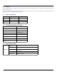
Table 13 Bit Descriptions Description (if bit is set to 1) Bit Word 63 0 Multiword DMA mode 0 is supported. 1 Multiword DMA mode 1 is supported. 2 Multiword DMA mode 2 is supported. 8 Multiword DMA mode 0 is currently active. 9 Multiword DMA mode 1 is currently active. 10 Multiword DMA mode 2 is currently active. Bit Word 88 0 Ultra DMA mode 0 is supported. 1 Ultra DMA mode 1 is supported. 2 Ultra DMA mode 2 is supported. 3 Ultra DMA mode 3 is supported.
4.3.2 Set Features command This command controls the implementation of various features that the drive supports. When the drive receives this command, it sets BSY, checks the contents of the Features register, clears BSY and generates an interrupt. If the value in the register does not represent a feature that the drive supports, the command is aborted. Power-on default has the read look-ahead and write caching features enabled.
4.3.3 S.M.A.R.T. commands S.M.A.R.T. provides near-term failure prediction for disk drives. When S.M.A.R.T. is enabled, the drive monitors predetermined drive attributes that are susceptible to degradation over time. If self-monitoring determines that a failure is likely, S.M.A.R.T. makes a status report available to the host. Not all failures are predictable. S.M.A.R.T. predictability is limited to the attributes the drive can monitor. For more information on S.M.A.R.T.
Seagate Technology LLC AMERICAS Seagate Technology LLC 10200 South De Anza Boulevard, Cupertino, California 95014, United States, 408-658-1000 ASIA/PACIFIC Seagate Singapore International Headquarters Pte. Ltd. 7000 Ang Mo Kio Avenue 5, Singapore 569877, 65-6485-3888 EUROPE, MIDDLE EAST AND AFRICA Seagate Technology SAS 16-18 rue du Dôme, 92100 Boulogne-Billancourt, France, 33 1-4186 10 00 Publication Number: 100804767, Rev.