v6 SATA Product Manual Standard models ST6000NE0023 ST4000NE0025 ST2000NE0025 100803998, Rev.
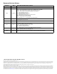
Document Revision History Revision Date Pages affected and Description of changes Rev. A 10/07/2016 Initial release. Rev. B 10/26/2016 fc:, 4-7: Broke out 2TB specs 5 & 7: Revised 2TB Sustained data transfer rate (MiB/s max) to 195 MiB/s 6 & 16: Revised Non-Op vibe to (4Hz/.03g2/Hz & 100Hz/.
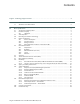
Contents Seagate® Technology Support Services . . . . . . . . . . . . . . . . . . . . . . . . . . . . . . . . . . . . . . . . . . . . . . . . . . . . . . . . . . . . . . . 4 1.0 Introduction. . . . . . . . . . . . . . . . . . . . . . . . . . . . . . . . . . . . . . . . . . . . . . . . . . . . . . . . . . . . . . . . . . . . . . . . . . . . . . . . . 5 1.1 About the Serial ATA interface . . . . . . . . . . . . . . . . . . . . . . . . . . . . . . . . . . . . . . . . . . . . . . . . . . . . . . . . . . . . .
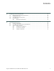
Contents 3.0 Configuring and mounting the drive . . . . . . . . . . . . . . . . . . . . . . . . . . . . . . . . . . . . . . . . . . . . . . . . . . . . . . . . . 25 3.1 Handling and static-discharge precautions . . . . . . . . . . . . . . . . . . . . . . . . . . . . . . . . . . . . . . . . . . . . . . . . . . . 25 3.2 Configuring the drive . . . . . . . . . . . . . . . . . . . . . . . . . . . . . . . . . . . . . . . . . . . . . . . . . . . . . . . . . . . . . . . . . . . . . . . . 25 3.
Seagate Technology Support Services ® For information regarding online support and services, visit: http://www.seagate.com/contacts/ For information regarding Warranty Support, visit: http://www.seagate.com/support/warranty-and-replacements/ For information regarding data recovery services, visit: http://www.seagate.com/services-software/recover/ For Seagate OEM, Distribution partner and reseller portals, visit: http://www.seagate.com/partners/ Seagate IronWolf Pro v6 Serial ATA Product Manual, Rev.
1.0 Introduction This manual describes the functional, mechanical and interface specifications for the following: Seagate® IronWolf™ Pro v6 Serial ATA model drives:. Standard models ST6000NE0023 ST4000NE0025 ST2000NE0025 These drives provide the following key features: • 7200 RPM spindle speed. • Full-track multiple-sector transfer capability without local processor intervention. • High instantaneous (burst) data-transfer rates (up to 600MB per second).
2.0 Drive specifications Unless otherwise noted, all specifications are measured under ambient conditions, at 25°C, and nominal power. For convenience, the phrases the drive and this drive are used throughout this manual to indicate the following drive models: Standard models ST6000NE0023 2.1 ST4000NE0025 ST2000NE0025 Specification summary tables The specifications listed in the following tables are for quick reference.
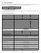
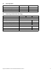
Drive specification ST6000NE0023 ST4000NE0025 ST2000NE0025 Vibration, operating 5–22 Hz: 0.25 Gs, Limited displacement 22–350 Hz: 0.50 Gs 350–500 Hz: 0.25 Gs Operation Rotational vibration 20–1500Hz: 12.5 rads/s² 2–500 Hz: 2Hz/.001g2/Hz 4Hz/.03g2/Hz 100Hz/.03g2/Hz 500Hz/.001g2/Hz Vibration, non-operating (Random psd) Drive acoustics, sound power (bels) Idle** 2.8 (typical) 3.0 (max) 2.2 (typical) 2.4 (max) Performance seek 3.2 (typical) 3.4 (max) 2.6 (typical) 2.
2.3 Start/stop times 4TB-6TB models 2TB model Power-on to Ready (sec) (typ/max) 23/30 17 Standby to Ready (sec) (typ/max) 23/30 17 Ready to spindle stop (sec) (max) 23 12 2.4 Recording and interface technology Models 6TB Interface 4TB 2TB Serial ATA (SATA) Recording method Perpendicular Recording density, KBPI (Kb/in max) 1984 1936 Track density, KTPI (ktracks/in avg) 370 330 Areal density (Gb/in2 avg) 732 651 Spindle speed (RPM) (± 0.
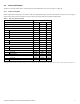
2.5 Power specifications The drive receives DC power (+5V or +12V) through a native SATA power connector. See Figure 3 on page 25. 2.5.1 Power consumption Power requirements for the drives are listed in Table 2 through Table 4. Typical power measurements are based on an average of drives tested, under nominal conditions, using 5.0V and 12.0V input voltage at 25°C ambient temperature. Table 2 DC power requirements (6TB) 6.
Table 3 DC power requirements (4TB) 6.0Gb mode Voltage +5V +12V Watts Regulation ± 5% ± 10% Total Avg Idle Current * 0.205 0.369 5.45 Idle_A 0.200 0.393 5.70 Idle_B 0.133 0.330 4.63 Idle_C 0.141 0.202 3.13 Standby 0.125 0.001 0.63 Typical DC 0.234 0.724 9.86 Maximum DC 0.238 0.734 10.00 Typical DC 0.245 0.692 9.52 Maximum DC 0.248 0.701 9.65 Typical DC 0.505 0.402 7.35 Maximum DC 0.512 0.407 7.45 Typical DC 0.443 0.427 7.33 Maximum DC 0.448 0.
Table 4 2TB Drive DC power requirements 6.0Gb mode Voltage +5V +12V Watts Regulation ± 5% ± 10% Total Avg Idle Current * 0.288 0.267 4.64 Idle_A 0.287 0.265 4.61 Idle_B 0.172 0.236 3.70 Idle_C 0.181 0.145 2.64 Standby 0.162 0.000 0.82 Typical DC 0.311 0.562 8.30 Maximum DC 0.317 0.569 8.41 Typical DC 0.320 0.557 8.29 Maximum DC 0.326 0.567 8.
2.5.1.1 Figure 1. 2.5.2 Typical current profiles Typical 5V and 12V startup and operation current profile Conducted noise Input noise ripple is measured at the host system power supply across an equivalent 80-ohm resistive load on the +12 V line or an equivalent 15-ohm resistive load on the +5V line. • Using 12V power, the drive is expected to operate with a maximum of 120mV peak-to-peak square-wave injected noise at up to 10MHz.
2.5.4 Extended Power Conditions - PowerChoiceTM The Power Choice features are supported on 4TB & 6TB models. Utilizing the load/unload architecture a programmable power management interface is provided to tailor systems for reduced power consumption and performance requirements. The table below lists the supported power conditions available in PowerChoice.
PowerChoice Manufacture Default Power Condition Timer Values Default power condition timer values have been established to assure product reliability and data integrity. A minimum timer value threshold of two minutes ensures the appropriate amount of background drive maintenance activities occur. Attempting to set a timer values less than the specified minimum timer value threshold will result in an aborted EPC "Set Power Condition Timer" subcommand.
2.6 Environmental limits Temperature and humidity values experienced by the drive must be such that condensation does not occur on any drive part. Altitude and atmospheric pressure specifications are referenced to a standard day at 58.7°F (14.8°C). To maintain optimal performance drives should be run at nominal drive temperatures and humidity. Note 2.6.1 Temperature a. Operating 41°F to 140°F (5°C to 60°C) drive case temperature range with a maximum temperature gradient of 36°F (20°C) per hour.
2.6.4 Shock All shock specifications assume that the drive is mounted securely with the input shock applied at the drive mounting screws. Shock may be applied in the X, Y or Z axis. 2.6.4.1 Operating shock These drives comply with the performance levels specified in this document when subjected to a maximum operating shock of 70 Gs (read) and 40 Gs (write) based on half-sine shock pulses of 2ms. Shocks should not be repeated more than two times per second. 2.6.4.
2.7 Acoustics Drive acoustics are measured as overall A-weighted acoustic sound power levels (no pure tones). All measurements are consistent with ISO document 7779. Sound power measurements are taken under essentially free-field conditions over a reflecting plane. For all tests, the drive is oriented with the cover facing upward. For seek mode tests, the drive is placed in seek mode only. The number of seeks per second is defined by the following equation: Note (Number of seeks per second = 0.
2.10 Reliability 2.10.1 Annualized Failure Rate (AFR) and Mean Time Between Failures (MTBF) The production disk drive shall achieve an annualized failure-rate of 0.73% (MTBF of 1,200,000 hours) over a 5 year service life when used in Enterprise Storage field conditions as limited by the following: • 8760 power-on hours per year.
Capacity; Legal Rights; Indemnity. You represent to SRS that you are of the legal age of majority in your state or country of residence, with the full capacity to agree to these Program Terms. You warrant that you are the legal owner or the authorized representative of the legal owner of the device you submit to SRS (the “Device”) and data.
Dispute Resolution. The parties will attempt to resolve any dispute arising out of or related to these Program Terms or any data recovery services requested or attempted hereunder through good faith negotiation. To the extent permitted by applicable law, if the parties are unable to resolve the dispute through good faith negotiation, then the dispute will be submitted to final and binding arbitration with the Judicial Arbitration and Mediation Services.
2.12.4 South Korean KC Certification Mark The South Korean KC Certification Mark means the drives comply with paragraph 1 of Article 11 of the Electromagnetic Compatibility control Regulation and meet the Electromagnetic Compatibility (EMC) Framework requirements of the Radio Research Agency (RRA) Communications Commission, Republic of Korea.These drives have been tested and comply with the Electromagnetic Interference/ Electromagnetic Susceptibility (EMI/EMS) for Class B products.
2.13 Environmental protection Seagate designs its products to meet environmental protection requirements worldwide, including regulations restricting certain chemical substances. 2.13.1 European Union Restriction of Hazardous Substance Law 2.13.1.1 Restriction of Hazardous Substances in Electrical and Electronic Equipment Seagate drives are designed to be compliant with the European Union RoHS "Recast" Directive 2011/65/EU (RoHS 2) as amended by Directive (EU) 2015/863.
2.13.3 Taiwan Requirements — Taiwan RoHS Taiwan RoHS refers to the Taiwan Bureau of Standards, Metrology and Inspection’s (BSMI) requirements in standard CNS 15663, Guidance to reduction of the restricted chemical substances in electrical and electronic equipment. Seagate products must comply with the “Marking of presence” requirements in Section 5 of CNS 15663, effective January 1, 2018. This product is Taiwan RoHS compliant. The following table meets the Section 5 “Marking of presence” requirements.
2.
3.0 Configuring and mounting the drive This section contains the specifications and instructions for configuring and mounting the drive. 3.1 Handling and static-discharge precautions After unpacking, and before installation, the drive may be exposed to potential handling and electrostatic discharge (ESD) hazards. Observe the following standard handling and static-discharge precautions: Caution 3.
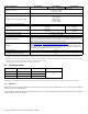
3.4 Drive mounting Users can mount the drive in any orientation using four screws in the side-mounting holes or four screws in the bottom-mounting holes. See Figures 4 & 5 for drive mounting dimensions. Follow these important mounting precautions when mounting the drive: • Allow a minimum clearance of 0.030 in (0.76mm) around the entire perimeter of the drive for cooling. • Use only 6-32 UNC mounting screws. • The screws should be inserted no more than 0.140 in (3.
0.14 0.14 Figure 5. Note Mounting configuration dimensions (2TB) The image is for mechanical dimension reference only and may not represent the actual drive. Seagate IronWolf Pro v6 Serial ATA Product Manual, Rev.
4.0 Serial ATA (SATA) interface These drives use the industry-standard Serial ATA interface that supports FIS data transfers. It supports ATA programmed input/ output (PIO) modes 0–4; multiword DMA modes 0–2, and Ultra DMA modes 0–6. For detailed information about the Serial ATA interface, refer to the “Serial ATA: High Speed Serialized AT Attachment” specification. 4.
4.3 Supported ATA commands The following table lists Serial ATA standard commands that the drive supports. For a detailed description of the ATA commands, refer to the Serial ATA: High Speed Serialized AT Attachment specification. See “S.M.A.R.T. commands” on page 35.for details and subcommands used in the S.M.A.R.T. implementation.
Command name Command code (in hex) Seek 70H Set Date & Time Ext 77H Set Features EFH Set Multiple Mode C6H Sleep E6H S.M.A.R.T. Disable Operations B0H / D9H S.M.A.R.T. Enable/Disable Autosave B0H / D2H S.M.A.R.T. Enable Operations B0H / D8H S.M.A.R.T. Execute Offline B0H / D4H S.M.A.R.T. Read Attribute Thresholds B0H / D1H S.M.A.R.T. Read Data B0H / D0H S.M.A.R.T. Read Log Sector B0H / D5H S.M.A.R.T. Return Status B0H / DAH S.M.A.R.T. Save Attribute Values B0H / D3H S.M.A.R.T.
4.3.1 Identify Device command The Identify Device command (command code ECH) transfers information about the drive to the host following power up. The data is organized as a single 512-byte block of data, whose contents are shown in Table 10 on page 29. All reserved bits or words should be set to zero. Parameters listed with an “x” are drive-specific or vary with the state of the drive. See Section 2.0 on page 6 for default parameter settings.
Word Description Value 64 Advanced PIO modes supported (modes 3 and 4 supported) 0003H 65 Minimum multiword DMA transfer cycle time per word (120 ns) 0078H 66 Recommended multiword DMA transfer cycle time per word (120 ns) 0078H 67 Minimum PIO cycle time without IORDY flow control (240 ns) 0078H 68 Minimum PIO cycle time with IORDY flow control (120 ns) 0078H 69 Additional supported 00008H 70–74 ATA-reserved 0000H 75 Queue depth 001FH 76 Serial ATA capabilities 8D0EH 77 Reserv
Word Description Value 160–205 ATA-reserved 0000H 206 SCT Command Transport command set. If bit 0 is set to one, then the device supports SCT Command Transport. Bits 7:2 indicate individual SCT feature support. xxBDH 207-254 ATA-reserved 0000H 255 Integrity word xxA5H See the bit descriptions below for words 63, 84, and 88 of the Identify Drive data. Note Description (if bit is set to 1) Bit Word 63 0 Multiword DMA mode 0 is supported. 1 Multiword DMA mode 1 is supported.
4.3.2 Set Features command This command controls the implementation of various features that the drive supports. When the drive receives this command, it sets BSY, checks the contents of the Features register, clears BSY and generates an interrupt. If the value in the register does not represent a feature that the drive supports, the command is aborted. Power-on default has the read look-ahead and write caching features enabled.
4.3.3 S.M.A.R.T. commands S.M.A.R.T. provides near-term failure prediction for disk drives. When S.M.A.R.T. is enabled, the drive monitors predetermined drive attributes that are susceptible to degradation over time. If self-monitoring determines that a failure is likely, S.M.A.R.T. makes a status report available to the host. Not all failures are predictable. S.M.A.R.T. predictability is limited to the attributes the drive can monitor. For more information on S.M.A.R.T.
Seagate Technology LLC AMERICAS Seagate Technology LLC 10200 South De Anza Boulevard, Cupertino, California 95014, United States, 408-658-1000 ASIA/PACIFIC Seagate Singapore International Headquarters Pte. Ltd. 7000 Ang Mo Kio Avenue 5, Singapore 569877, 65-6485-3888 EUROPE, MIDDLE EAST AND AFRICA Seagate Technology SAS 16-18 rue du Dôme, 92100 Boulogne-Billancourt, France, 33 1-4186 10 00 Publication Number: 100803998, Rev.