Product Manual Momentus 4200.2 ® ST9120824A ST9100825A ST980829A ST960812A ST950814A ST9402112A ST930218A 100367124 Rev.
©2004-2007, Seagate Technology LLC All rights reserved. Publication number: 100367124, Rev. C August 2007 Seagate, Seagate Technology and the Wave logo are registered trademarks of Seagate Technology LLC in the United States and/or other countries. Momentus, SeagateSeaBOARD, SeaFONE, SeaTDD, and SeaTools are either trademarks or registered trademarks of Seagate Technology LLC or one of its affiliated companies in the United States and/ or other countries.
Contents 1.0 Introduction. . . . . . . . . . . . . . . . . . . . . . . . . . . . . . . . . . . . . . . . . . . . . . . . . . . . . . . . . . . . . . . . . . . 1 2.0 Drive specifications . . . . . . . . . . . . . . . . . . . . . . . . . . . . . . . . . . . . . . . . . . . . . . . . . . . . . . . . . . . . 3 2.1 Specification summary . . . . . . . . . . . . . . . . . . . . . . . . . . . . . . . . . . . . . . . . . . . . . . . . . . . . 3 2.2 Formatted capacity . . . . . . . . . . . . . . . . . . . . . . .
ii Momentus 4200.2 Product Manual, Rev.
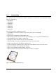
List of Figures Figure 1. Figure 2. Figure 3. Figure 4. Momentus 4200.2 PATA disc drive . . . . . . . . . . . . . . . . . . . . . . . . . . . . . . . . . . . . . . . . . . . . . 1 Typical 5V startup and operation current profile . . . . . . . . . . . . . . . . . . . . . . . . . . . . . . . . . . . 10 Jumper settings . . . . . . . . . . . . . . . . . . . . . . . . . . . . . . . . . . . . . . . . . . . . . . . . . . . . . . . . . . . 20 Mounting dimensions—top, side and end view . . . . . . . . . . . . . . .
iv Momentus 4200.2 Product Manual, Rev.
1.0 Introduction This manual describes the functional, mechanical and interface specifications for the following Seagate® Momentus 4200.2 drives: • ST9120824A • ST9100825A • ST980829A • ST960812A • ST950814A • ST9402112A • ST930218A These drives provide the following key features: • 4,200-RPM-Class Performance spindle speed. Actual spindle speed is 5,400 RPM. • 8-Mbyte buffer. • Quiet operation. Fluid Dynamic Bearing (FDB) motor.
2 Momentus 4200.2 Product Manual, Rev.
2.0 Drive specifications Unless otherwise noted, all specifications are measured under ambient conditions, at 25°C, and nominal power. For convenience, the phrases the drive and this drive are used throughout this manual to indicate ST9120824A, ST9100825A, ST980829A, ST960812A, ST950814A, ST9402112A, and ST930218A model drives. 2.1 Specification summary The specifications listed in this table are for quick reference.
Table 1: Specifications for 120, 100, and 80 GB models Drive specification ST9120824A ST9100825A Read/write power (typical) Read: 1.80 watts; Write: 1.80 watts Idle mode (low power, typical) 0.80 watts Standby mode 0.26 watts (typical)*** Sleep mode 0.
Table 1: Specifications for 60, 50, 40, and 30 GB models Drive specification ST960812A ST950814A ST9402112A ST930218A Formatted Gbytes (512 bytes/sector)* 60 50 40 30 Guaranteed sectors 117,210,240 97,692,174 78,140,160 58,605,120 Bytes per sector 512 Physical read/write heads 2 2 2 1 Discs 1 1 1 1 Cache (Mbytes) 8 Recording density, BPI (bits/inch typical) 778k Track density. TPI (tracks/inch typical 126k 2 Areal density (Gbits/inch max) 98.
Table 1: Specifications for 60, 50, 40, and 30 GB models Drive specification ST960812A ST950814A Shock, nonoperating (Gs max at 2 msec) 800 Shock, nonoperating (Gs max at 1 msec) 900 Shock, nonoperating (Gs max at 0.5 msec) 400 Vibration, operating (max displacement may apply below 10 hz) 1.0 Gs (0 to peak, 5–500 Hz) Vibration, nonoperating (max displacement may apply below 22 hz) 5.0 Gs (0 to peak, 5–500 Hz) ST9402112A ST930218A Drive acoustics, sound power (bels), 2 disc Idle** 2.
2.2 Formatted capacity Model Formatted capacity* Guaranteed sectors Bytes per sector ST9120824A 120 Gbytes 234,441,648 512 ST9100825A 100 Gbytes 195,371,568 512 ST980829A 80 Gbytes 156,301,488 512 ST960812A 60 Gbytes 117,210,240 512 ST950814A 50 Gbytes 97,692,174 512 ST9402112A 40 Gbytes 78,140,160 512 ST930218A 30 Gbytes 58,605,120 512 *One Gbyte equals one billion bytes when referring to hard drive capacity.
2.5 Recording and interface technology Technology Specification Interface Parallel ATA Recording method RLL 0,11 Recording density BPI (bits/inch typical) 778k Track density TPI (tracks/inch typical) 126k Areal density (Mbits/inch2 max) 98.2 Spindle speed (RPM) (± 0.
2.8 Time to ready Time to ready Typical Max @ 25°C Power-on to Ready (sec) 3.5 8.0 Standby to Ready (sec) 3.0 8.0 2.9 Power specifications The drive receives DC power (+5V) through the interface connector. 2.9.1 Power consumption Power requirements for the drives are listed in the table on page 9. Typical power measurements are based on an average of drives tested, under nominal conditions, at 25°C ambient temperature.
2.9.1.1 Typical current profile Figure 2. Typical 5V startup and operation current profile 2.9.2 Conducted noise Input noise ripple is measured at the host system power supply across an equivalent 15-ohm resistive load on the +5 volt line. Using 5-volt power, the drive is expected to operate with a maximum of 100 mV peak-to-peak square-wave injected noise at up to 10 MHz. Note. Equivalent resistance is calculated by dividing the nominal voltage by the typical RMS read/write current. 2.9.
2.9.4 Power-management modes The drive provides programmable power management to provide greater energy efficiency. In most systems, you can control power management through the system setup program.
2.10 Environmental specifications 2.10.1 Ambient temperature Ambient temperature is defined as the temperature of the environment immediately surrounding the drive. Actual drive case temperature should not exceed 65°C (149°F) within the operating ambient conditions. Above 1,000 feet (305 meters), the maximum temperature is derated linearly by 1°C every 1000 feet. Operating Nonoperating 2.10.
2.10.5 Shock All shock specifications assume that the drive is mounted securely with the input shock applied at the drive mounting screws. Shock may be applied in the X, Y or Z axis. 2.10.5.1 Operating shock These drives comply with the performance levels specified in this document when subjected to a maximum operating shock of 250 Gs based on half-sine shock pulses of 2 msec. Shocks should not be repeated more than two times per second. 2.10.5.
2.11 Acoustics Drive acoustics are measured as overall A-weighted acoustic sound power levels (no pure tones). All measurements are consistent with ISO document 7779. Sound power measurements are taken under essentially free-field conditions over a reflecting plane. For all tests, the drive is oriented with the cover facing upward. Note. For seek mode tests, the drive is placed in seek mode only. The number of seeks per second is defined by the following equation: Number of seeks per second = 0.
2.13 Reliability Measurement type Specification Nonrecoverable read errors 1 per 1014 bits read, max. Annualized Failure Rate (AFR) 0.
Korean RRL If these drives have the Korea Ministry of Information and Communication (MIC) logo, they comply with paragraph 1 of Article 11 of the Electromagnetic Compatibility control Regulation and meet the Electromagnetic Compatibility (EMC) Framework requirements of the Radio Research Laboratory (RRL) Ministry of Information and Communication Republic of Korea. These drives have been tested and comply with the Electromagnetic Interference/Electromagnetic Susceptibility (EMI/EMS) for Class B products.
2.15 Environmental protection Seagate designs its products to meet environmental protection requirements worldwide, including regulations restricting certain chemical substances. European Union Restriction of Hazardous Substances (RoHS) The European Union Restriction of Hazardous Substances (RoHS) Directive restricts the presence of chemical substances, including Lead (Pb), in electronic products effective July 2006. A number of parts and materials in Seagate products are procured from external suppliers.
18 Momentus 4200.2 Product Manual, Rev.
3.0 Configuring and mounting the drive This section contains the specifications and instructions for configuring and mounting the drive. 3.1 Handling and static discharge precautions After unpacking, and before installation, the drive may be exposed to potential handling and electrostatic discharge (ESD) hazards.
3.2 Jumper settings 3.2.1 Master/slave configuration Use the options jumper block shown in Figure 3 to configure the drive for operation. This jumper block is the 4pin header adjacent to pins 1 and 2 of the I/O signal pins. For additional information about using the Cable select option, see Section 3.2.2. The “Master or single drive” option is the factory default setting. Drive is master (or single drive) Drive is slave Cable select Figure 3. Jumper settings 3.2.
3.3 Drive mounting You can mount the drive using four screws in the side-mounting holes or four screws in the bottom-mounting holes. See Figure 4 for drive mounting dimensions (dimensions in inches with mm in parentheses). Follow these important mounting precautions when mounting the drive: • Allow a minimum clearance of 0.030 inches (0.76 mm) around the entire perimeter of the drive for cooling. • Use only M3 x 0.5 mounting screws. • Do not overtighten the mounting screws (maximum torque: 4.0 inch-lb).
22 Momentus 4200.2 Product Manual, Rev.
4.0 ATA interface These drives use the industry-standard ATA task file interface that supports 16-bit data transfers. It supports ATA programmed input/output (PIO) modes 0–4; multiword DMA modes 0–2, and Ultra DMA modes 0–5. The drive also supports the use of the IORDY signal to provide reliable high-speed data transfers.
4.1.1 Supported ATA commands The following table lists ATA-standard commands that the drive supports. For a detailed description of the ATA commands, refer to the Draft ATA-6 Standard.
Table 7: Supported commands Command name Command code (in hex) Security Unlock F2H Seek 70H Set Drive Parameters 91H Set Features EFH Set Max Address F9H Note: Individual Set Max commands are identified by the value placed in the Set Max Features register as defined to the right. Address: Password: Lock: Unlock: Freeze Lock: Set Multiple Mode C6H Sleep 99H, E6H S.M.A.R.T.
Table 7: Supported commands Command name Command code (in hex) Security Freeze Lock F5H Security Disable Password F6H 4.1.2 Identify Device command The Identify Device command (command code ECH) transfers information about the drive to the host following power up. The data is organized as a single 512-byte block of data, whose contents are shown in Table 7 on page 24. All reserved bits or words should be set to zero.
Word Description Value 51 PIO data-transfer cycle timing mode 0200H 52 Retired 0200H 53 Words 54–58, 64–70 and 88 are valid 0007H 54 Number of current logical cylinders xxxxH 55 Number of current logical heads xxxxH 56 Number of current logical sectors per logical track xxxxH 57–58 Current capacity in sectors xxxxH 59 Number of sectors transferred during a Read Multiple or Write Multiple command xxxxH 60–61 Total number of user-addressable LBA sectors available (see Section 2.
Word Description Value 90 Enhanced security erase time 0000H 91 Advanced power management value 0040H 92 Master password revision code FFFEH 93 Hardware reset value (see description following this table) xxxxH 94 Auto acoustic management setting xxxxH 95–127 ATA-reserved 0000H 128 Security status 0001H 129–159 Seagate-reserved xxxxH 160–254 ATA-reserved 0000H 255 Integrity word xxA5H Note.
13 4.1.3 1 = 80-conductor cable detected, CBLID above VIH 0 = 40-conductor cable detected, CBLID below VIL Set Features command This command controls the implementation of various features that the drive supports. When the drive receives this command, it sets BSY, checks the contents of the Features register, clears BSY and generates an interrupt. If the value in the register does not represent a feature that the drive supports, the command is aborted.
30 Momentus 4200.2 Product Manual, Rev.
5.0 Compatibility summary 5.1 Installation considerations Many of today’s mobile computers have been designed to make it possible for the end user to replace the hard drive. Refer to your system’s user manual for the location of the hard drive compartment and the specific instructions regarding replacement. Refer to your system manufacturer’s support website for the most up-todate information. Read and follow all instructions regarding the proper steps to be taken when replacing the system hard drive.
5.2 System Compatibility Seagate Product Assurance has tested Momentus drives in the systems listed in Table 9. Testing included multiple BIOS versions and operating systems. This testing was done to demonstrate compatibility with various hardware and software configurations. Hardware and software combinations, other than those tested, may also be compatible with this drive.
5.3 BIOS versions tested The following list indicates the types of BIOS Seagate tested during the compatibility testing process. The list highlights the major BIOS manufacturers. Individual systems contain variations of these BIOS versions and were tested with regard to their implementation in the individual systems. Table 10: Vendor Tested BIOS versions Release Revision ACER 1.01 ACPI Ver. 1.20 AMI Various Apple 4.71F1 Apple 4.8.4F1 Award Various Various Compal 38118 v2.
5.4 Operating system versions tested This list indicates the types of Operating Systems Seagate tested during the compatibility testing process and highlights the major OS manufacturers. Several variations of the major operating systems have been tested. Table 11: Operating systems tested Manufacturer Version/Release Apple MacOS 9.22 Apple MacOS X 10.2.3 Microsoft MSDOS 6.
6.0 Seagate Technology support services Internet For information regarding Seagate products and services, visit www.seagate.com. Worldwide support is available 24 hours daily by email for your questions. Presales Support: Presales@Seagate.com Technical Support: DiscSupport@Seagate.com Warranty Support: http://www.seagate.com/support/service/index.html mySeagate my.seagate.com is the industry's first Web portal designed specifically for OEMs and distributors.
Customer Service Operations Warranty Service Seagate offers worldwide customer support for Seagate products. Seagate distributors, OEMs and other direct customers should contact their Seagate Customer Service Operations (CSO) representative for warrantyrelated issues. Resellers or end users of drive products should contact their place of purchase or Seagate warranty service for assistance. Have your serial number and model or part number available.
Index A acoustics 14 Active mode 11 agency certification (regulatory) 15 altitude 12 ambient conditions 3 ambient temperature 8, 12 Annualized Failure Rate (AFR) 4, 6, 15 areal density 8 ATA interface 23 ATA-standard commands 24 Australian C-Tick 16 autodetection 1 average seek time 8 discs 7 dissipation 9 Download Microcode 24 drive diagnostics 8 drive monitoring 1 drive self-test 1 E BIOS manufacturers 33 BPI 8 buffer 1, 8 burst 1 electrical fast transient 14 electromagnetic compatibility 15 Electroma
interface 8, 23 interface signals 23 interference 16 interleave 8 internal data-transfer rate OD 8 ISO document 7779 14 J power-management commands 25 power-management modes 11 Power-on to Ready 9 precautions 21 programmable power management 11 R noise 10 nominal power 3 nonoperating shock 13 nonoperating vibration 13 nonrecoverable read errors 15 radiated RF immunity 14 radio and television interference 16 radio frequency (RF) 14 random track location 9 Read Buffer 24 Read DMA 24 Read DMA Extended 24
Self refresh, low power 11 Service Life 15 servo electronics 9 Set Features 25 Set Features command 29 Set Max 25 Set Multiple Mode 25 shock 13 signals 23 single-track seeks 8 Sleep 9, 25 Sleep mode 11 software utilities 34 sound 14 specifications 3 spindle speed 8 Spinup 9 spinup power 9 Standby 9, 25 Standby Immediate 25 Standby mode 9, 11 Standby to Ready 9 static-discharge precautions 19 subassembly 16 support services 35 surge immunity 14 Write Buffer 25 Write DMA 25 Write DMA Extended 25 Write Multip
40 Momentus 4200.2 Product Manual, Rev.
Seagate Technology LLC 920 Disc Drive, Scotts Valley, California 95066-4544, USA Publication Number: 100367124, Rev. C, Printed in U.S.A.