.......................... ST9235 Family: .......................... ST9080A .......................... ST9145A, ST9145AG .......................... ST9235A, ST9235AG .......................... Installation Guide ..........................
Contents Read before you begin... . . . . . . . . . . . . . . 1 Installation overview . . . . . . . . . . . . . . . . . . . . 2 Setting master/slave jumpers . . . . . . . . . . . . . . .3 Connecting cables . . . . . . . . . . . . . . . . . . . . .3 Mounting the drive . . . . . . . . . . . . . . . . . . . . .5 Configuring system BIOS . . . . . . . . . . . . . . . . . . 5 Formatting and partitioning the drive . . . . . . . . . . . 8 Installation troubleshooting . . . . . . . . . . . . . . . .
ST9235 Family Installation Guide, Rev. B 1 Read before you begin... Note. Drives in the ST9235 family are usually installed in notebook or laptop systems. Special training or tools may be needed to service these computers. In some instances, opening the case may void your warranty. Be sure to review the terms and conditions of your system warranty before opening the system enclosure. Warning. Always power off and unplug your computer system before touching any internal components.
2 ST9235 Family Installation Guide, Rev. B Warranty. Contact your authorized Seagate distributor or dealer for warranty information. Maintenance and repair. Seagate drives do not require any preventive maintenance. The head/disc assembly is sealed and does not contain any user-serviceable components. Tampering with the factory seal voids the warranty. Seagate customer service centers are the only facilities authorized to service Seagate drives. Seagate does not sanction any third-party repair facilities.
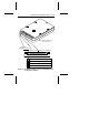
ST9235 Family Installation Guide, Rev. B 3 Setting master/slave jumpers Two drives may be controlled through a single drive controller cable with two connectors. In this case, one drive is designated as the master and the other is designated as the slave. As shown in Figure 1 on page 4, the jumpers on each drive must be set to identify which drive is master and which is slave. Connecting cables The ST9235 Family drives use a 44-pin AT interface connector cable with two rows of 22 female contacts on 0.
4 ST9235 Family Installation Guide, Rev. B Note. Drive is shown with circuit board up. Master/slave Pin 1 configuration jumpers Pin 20 removed for keying Circuit board A B C D Drive is master; no slave present Drive is master; Seagate slave drive present Drive is slave; Seagate master drive present Reserved positions (do not use) Figure 1.
ST9235 Family Installation Guide, Rev. B 5 Mounting the drive You can mount (and operate) a ST9235 family drive in any orientation. However, you must securely attach the drive to a rigid frame using four side-mounting screws or four bottom-mounting screws. Caution: To avoid damaging the drive: • Use M3X0.5 metric mounting screws only. • Do not insert mounting screws more than 0.150 inches (3.81 mm) into the mounting holes (except: 0.190 inches (4.
6 ST9235 Family Installation Guide, Rev. B drive types your BIOS supports. Another method is to run the FINDTYPE.EXE utility program, available from Seagate Technical Support services (on the SeaBOARD BBS) as described in Appendix C. The methods used to configure system BIOS vary from system to system. In many cases you can run a setup program from the DOS prompt. In other cases, you must initiate BIOS setup by pressing certain keys while the system is booting up.
ST9235 Family Installation Guide, Rev. B 7 table above. This value will be lower than the usable drive capacity. In a few situations, none of the drive types specified in your BIOS setup program will match your drive, and the setup program will not provide an opportunity to specify a custom drive type. In this case, consider the third option described above — allowing your ST9235 family drive to mimic one of the BIOS-supported drive types.
8 ST9235 Family Installation Guide, Rev. B your system BIOS may look for 4 bytes of ECC. If your system BIOS expects 4 bytes of ECC and the drive supplies a different number of bytes, some drive diagnostic programs may fail, typically resulting in time-out errors. Consult your system documentation or call your system dealer or manufacturer for information on configuring your system to receive 11 bytes of ECC. Formatting and partitioning the drive Caution.
ST9235 Family Installation Guide, Rev. B 9 High-level formatting Once the drive is partitioned, use the DOS FORMAT command (or equivalent utility program) to high-level format each of the drive partitions. This process verifies the information written by the low-level format and creates file allocation tables (used to catalog and access files). Consult your DOS manual for FORMAT command options.
10 ST9235 Family Installation Guide, Rev. B location. Make sure pin 1 on the interface cable connector is connected to pin 1 on the drive interface connector and pin 1 on the host connector. Refer to Figure 1 on page 4 for the location of pin 1 on the drive interface connector. • Check all cards. Make sure all cards are secured in the expansion slots on the motherboard. Full size (16-bit) cards cannot be plugged into half-size (8-bit) slots.
ST9235 Family Installation Guide, Rev. B 11 Appendix A.
12 ST9235 Family Installation Guide, Rev. B Appendix B. Mounting dimension drawings Dimensions are in inches (mm) 0.492 ± 0.005 (12.50 ± 0.13) 0.066 ± 0.020 (1.68 ± 0.51) 0.000 0.100 ± 0.010 (2.54 ± 0.25) 0.146 +0.011, –0.008 (3.71 +0.28, –0.20) 4X 3 mm × 0.5 mm 0.15 in (3.81 mm) min. full thread 1.227 ± 0.025 (31.17 ± 0.64) 4.010 (101.85) max 1.500 ± 0.010 (38.10 ± 0.25) 0.000 1.375 ± 0.015 (34.93 ± 0.38) 0.155 ± 0.025 (3.94 ± 0.64) 0.000 0.275 ± 0.025 (6.99 ± 0.64) 2.760 (70.10) max 2.430 ± 0.
ST9235 Family Installation Guide, Rev. B 13 Dimensions are in inches (mm) 2.875 (73.03) 1.375 (34.93) 0.750 max (19.05) 0.157 ± 0.020 (3.99 ± 0.51) 0.000 0.118 (3.00) 4X 3 mm × 0.5 mm, 0.15 in (3.81 mm) min full thread 1.227 ± 0.025 (31.17 ± 0.64) 0.146 +0.011, –0.008 (3.71 +0.28, –0.20) 4.010 max (101.85) 2.875 (73.03) 0.000 1.375 (34.93) 0.000 0.160 (4.06) 2.590 (65.79) 2.760 max (70.10) 4X 3 mm × 0.5 mm, 0.15 in (3.81 mm) min full thread 0.394 ± 0.025 (10.01 ± 0.64) Pin 1 0.079 (2.
14 ST9235 Family Installation Guide, Rev. B Dimensions are in inches (mm) 0.750 (19.05) max 0.066 ± 0.020 (1.68 ± 0.51) 0.039 ± 0.020 (0.99 ± 0.51) 0.000 4X 3 mm × 0.5 mm 0.15 in. (3.81 mm) min. full thread 0.230 ± 0.010 (5.84 ± 0.25) 0.118 ± 0.010 (3.00 ± 0.25) 0.146 +0.011, –0.008 (3.71 +0.28, –0.20) 1.227 ± 0.025 (31.17 ± 0.64) 4.010 (101.85) max 1.500 ± 0.010 (38.10 ± 0.25) 0.000 1.375 ± 0.015 (34.93 ± 0.38) 0.155 ± 0.025 (3.94 ± 0.64) 0.000 0.275 ± 0.025 (6.99 ± 0.64) 0.239 ± 0.025 (6.07 ± 0.
ST9235 Family Installation Guide, Rev. B 15 Appendix C. Technical support services Product technical support is available for all Seagate products by calling the SeaFAX, SeaFONE, SeaTDD and SeaBOARD services described below. These services are free, but long-distance charges (if any) are paid by the user. SeaFAX. 408/438-2620 You can use a touch-tone telephone to access Seagate’s automated FAX system and select technical support information by return FAX.
16 ST9235 Family Installation Guide, Rev. B • A directory of information and helpful utility programs that you can download to your own computer. • The FINDTYPE.EXE utility program, which can be very useful in drive installation. It compares the drive’s geometry with all geometries supported by your system BIOS. This program either signals that an exact match exists between the drive geometry and the system BIOS, or recommends the closest drive type supported by your system BIOS.
Seagate Technology, Inc. 920 Disc Drive, Scotts Valley, CA 95066, USA Publication Number: 36216-001, Rev.