Product Manual LD25 Series 5400.2 PATA SATA ST980210A ST960210A ST940210A ST980210AS ST960210AS ST940210AS ST920210AS 100433447 Rev.
©2007, Seagate Technology LLC All rights reserved. Publication number: 100433447, Rev. C August 2007 Seagate and Seagate Technology are registered trademarks of Seagate Technology LLC. SeaBOARD, SeaFONE, SeaTDD, SeaTools, and the Wave logo are either registered trademarks or trademarks of Seagate Technology LLC. Other product names are registered trademarks or trademarks of their owners. Seagate reserves the right to change, without notice, product offerings or specifications.
Contents 1.0 Introduction. . . . . . . . . . . . . . . . . . . . . . . . . . . . . . . . . . . . . . . . . . . . . . . . . . . . . . . . . . . . . . . . . . . 1 2.0 Drive specifications . . . . . . . . . . . . . . . . . . . . . . . . . . . . . . . . . . . . . . . . . . . . . . . . . . . . . . . . . . . . 3 2.1 Specification summaries . . . . . . . . . . . . . . . . . . . . . . . . . . . . . . . . . . . . . . . . . . . . . . . . . . . 3 2.2 Formatted capacity . . . . . . . . . . . . . . . . . . . . . . .
.0 Interface . . . . . . . . . . . . . . . . . . . . . . . . . . . . . . . . . . . . . . . . . . . . . . . . . . . . . . . . . . . . . . . . . . . . . 4.1 Serial ATA (SATA) Interface . . . . . . . . . . . . . . . . . . . . . . . . . . . . . . . . . . . . . . . . . . . . . . . 4.1.1 Hot-Plug compatibility. . . . . . . . . . . . . . . . . . . . . . . . . . . . . . . . . . . . . . . . . . . . . 4.1.2 Serial ATA device plug connector pin definitions . . . . . . . . . . . . . . . . . . . . . . . . 4.
List of Figures Figure 1. Figure 2. Figure 3. Figure 4. Figure 5. Mounting dimensions—top, side and end view . . . . . . . . . . . . . . . . . . . . . . . . . . . . . . . . . . . Breather filter hole location . . . . . . . . . . . . . . . . . . . . . . . . . . . . . . . . . . . . . . . . . . . . . . . . . . . SATA connectors. . . . . . . . . . . . . . . . . . . . . . . . . . . . . . . . . . . . . . . . . . . . . . . . . . . . . . . . . . Attaching SATA cabling . . . . . . . . . . . . . . . . . . . . . . .
iv LD25 Series 5400.2 Product Manual, Rev.
1.0 Introduction This manual describes the functional, mechanical and interface specifications for the following Seagate® LD25 Series 5400.2 drives: Parallel ATA (PATA) Serial ATA (SATA) ST980210A ST980210AS ST960210A ST960210AS ST940210A ST940210AS ST920210AS Seagate LD25 Series 5400.2 drives are 2.
2 LD25 Series 5400.2 Product Manual, Rev.
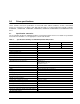
2.0 Drive specifications Unless otherwise noted, all specifications are measured under ambient conditions, at 25°C, and nominal power. For convenience, the phrases the drive and this drive are used throughout this manual to indicate ST980210A, ST980210AS, ST960210A, ST960210AS, ST940210A, ST940210AS and ST920210AS model drives. 2.1 Specification summaries The specifications listed in the following two tables are provided for quick reference.
Table 1: Specification summary for ATA/PATA (Parallel ATA) models Drive specification ST980210A ST960210A Standby and sleep modes (watts, typical) ≤ 0.
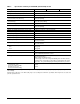
Table 2: Specifications for SATA (Serial ATA) models Drive specification ST980210AS ST960210AS ST940210AS ST920210AS Formatted Gbytes (512 bytes/sector)* 80 60 40 20 Guaranteed sectors 156,501,488 117,210,240 78,340,160 41,021,800 Bytes per sector 512 Default sectors per track 63 Default read/write heads 16 Default cylinders 16,383 Spindle speed (RPM) 5,400 Internal data transfer rate OD (Mbytes/sec max) >40 I/O data-transfer rate (Mbytes/sec max) 150 ATA data-transfer modes s
Table 2: Specifications for SATA (Serial ATA) models Drive specification ST980210AS ST960210AS ST940210AS ST920210AS Drive acoustics, sound power (Bels) Idle** 2.4 (typical) Seek 2.6 (typical) Nonrecoverable read errors 1 per 1014 bits read Annualized Failure Rate (AFR) <0.6% (Desktop and gaming: 2400 power-on-hours) <2.0% (PVR/DVR: 8760 power-on-hours) Warranty To determine the warranty for a specific drive, use a web browser to access the following web page: www.seagate.
2.4 Recording and interface technology Interface Parallel ATA Recording density BPI (bits/inch typical) 829,700 Track density TPI (tracks/inch typical) 143,600 Areal density (Gbits/inch2 max) 130 Spindle speed (RPM) (± 0.2%) 5,400 Internal data-transfer rate OD (Mbytes/sec max) >40 I/O data-transfer rate (Mbytes/sec max) PATA SATA 100 (Ultra DMA mode 5) 150 Interleave 1:1 Cache buffer 2 Mbytes (2,048 kbytes) 2.5 Physical characteristics Height (mm) (inches) 9.5 ± 0.2 0.374 ± 0.
2.6 Seek time Seek measurements are taken with nominal power at 25°C ambient temperature. All times are measured using drive diagnostics. The specifications below are defined as follows: • Track-to-track seek time is an average of all possible single-track seeks in both directions. • Average seek time is a true statistical random average of at least 5,000 measurements of seeks between random tracks, less overhead. Typical seek times (msec) Read Write Track-to-track 1.0 1.
2.8 Power specifications The drive receives DC power (+5V) through the 4-pin power connector. 2.8.1 Power consumption Power requirements for the drives are listed in the table on page 9. Typical power measurements are based on an average of drives tested, under nominal conditions, at 25°C ambient temperature. • Spinup power Spinup power is measured from the time of power-on to the time that the drive spindle reaches operating speed.
2.8.1.1 Typical current profile Figure 1. Typical 5V startup and operation current profile 2.8.2 Conducted noise Input noise ripple is measured at the host system power supply across an equivalent 15-ohm resistive load on the +5 volt line. Using 5-volt power, the drive is expected to operate with a maximum of 100 mV peak-to-peak square-wave injected noise at up to 10 MHz. Note. Equivalent resistance is calculated by dividing the nominal voltage by the typical RMS read/write current. 2.8.
2.8.4 Power-management modes The drive provides programmable power management to provide greater energy efficiency. In most systems, you can control power management through the system setup program.
2.9 Environmental specifications 2.9.1 Ambient temperature Ambient temperature is defined as the temperature of the environment immediately surrounding the drive. Actual drive case temperature should not exceed 65°C (149°F) within the operating ambient conditions. Above 1,000 feet (305 meters), the maximum temperature is derated linearly by 1°C every 1000 feet. Operating Nonoperating 2.9.
2.9.5 Shock All shock specifications assume that the drive is mounted securely with the input shock applied at the drive mounting screws. Shock may be applied in the X, Y or Z axis. 2.9.5.1 Operating shock These drives comply with the performance levels specified in this document when subjected to a maximum operating shock of 175 Gs based on half-sine shock pulses of 2 msec. Shocks should not be repeated more than two times per second. 2.9.5.
2.10 Acoustics Drive acoustics are measured as overall A-weighted acoustic sound power levels. All measurements are consistent with ISO document 7779. Sound power measurements are taken under essentially free-field conditions over a reflecting plane. For all tests, the drive is oriented with the cover facing upward. Note. For seek mode tests, the drive is placed in seek mode only. The number of seeks per second is defined by the following equation: (Number of seeks per second = 0.
2.12 Reliability Measurement type Specification Nonrecoverable read errors 1 per 1014 bits read, max. Annualized Failure Rate (AFR) <0.6% (Desktop and gaming: 2400 power-on-hours) <2.0% (PVR/DVR: 8760 power-on-hours) Load/Unload (L/UL) Controlled L/UL cycles (40°C, 50% Relative Humidity) Emergency L/UL cycles (40°C, 50% Relative Humidity) Warranty 50,000 20,000 To determine the warranty for a specific drive, use a web browser to access the following web page: www.seagate.
Korean RRL If these drives have the Korea Ministry of Information and Communication (MIC) logo, they comply with paragraph 1 of Article 11 of the Electromagnetic Compatibility control Regulation and meet the Electromagnetic Compatibility (EMC) Framework requirements of the Radio Research Laboratory (RRL) Ministry of Information and Communication Republic of Korea. These drives have been tested and comply with the Electromagnetic Interference/Electromagnetic Susceptibility (EMI/EMS) for Class B products.
2.14 Environmental protection Seagate designs its products to meet environmental protection requirements worldwide, including regulations restricting certain chemical substances. 2.14.1 European Union Restriction of Hazardous Substances (RoHS) The European Union Restriction of Hazardous Substances (RoHS) Directive restricts the presence of chemical substances, including Lead (Pb), in electronic products effective July 2006.
18 LD25 Series 5400.2 Product Manual, Rev.
3.0 Configuring and mounting the drive This section contains the specifications and instructions for configuring and mounting the drive. 3.1 Handling and static-discharge precautions After unpacking, and before installation, the drive may be exposed to potential handling and electrostatic discharge (ESD) hazards.
Measurements shown below are in inches. 1 DIMENSIONS PER EIA-720 OR SFF 8201 SPECIFICATION. 2 DIMENSIONS PER SFF 8212 OR SFF 8223. 3 DRIVE LENGTH W/ PATA IS 3.945±.057 (WORST CASE). DRIVE LENGTH W/ SATA IS 3.957±.062 (WORST CASE). 3.945 ± .010 (BASE) .157 ( .490 ) .217 ±.050 2 .217 ±.050 2 .399 C ( .673 ) OF CONN. DATUM B C OF DRIVE 1 2.750 ±.010 (BASE) ( .189 ) 2 SATA PATA 3 BASE 3.567 .551 1 1 2X M3 X 0.5-6H MOUNTING HOLES; BOTH SIDES .12 MIN FULL THREAD 0.148 ±.010 X 90 ( .
3.3 Breather filter hole precautions Observe the following breather filter hole precautions to ensure full functionality and prevent possible damage to the drive. Breather filter hole Do not cover, seal, or put any object in this hole. Figure 3 Breather filter hole location Caution: Do not cover, seal, or insert any object into this hole.
3.4 How to configure the drive See Section 3.4.1 on page 22 for SATA drives. See Section 3.4.2 on page 23 for PATA drives. 3.4.1 How to configure and connect Serial ATA (SATA) drives 3.4.1.1 How to configure the drive Each drive on the SATA interface connects in a point-to-point configuration with the SATA host adapter. There is no master/slave relationship because each drive is considered a master in a point-to-point relationships.
Each cable is keyed to ensure correct orientation. 3.4.2 How to configure Parallel ATA (PATA) drives Use the options jumper block shown in Figure 6 to configure the drive for operation. This jumper block is the 4-pin header adjacent to pins 1 and 2 of the I/O signal pins. For additional information about using the Cable select option, see Section 3.4.2.1.1. 3.4.2.1 How to configure the drive as a master or slave Refer to Figure 6 to set the master, slave, or cable select option.
24 LD25 Series 5400.2 Product Manual, Rev.
4.0 Interface Interface Refer to SATA Section 4.1 beginning on page 26 PATA Section 4.2 beginning on page 28 The following sections apply to both SATA and PATA drives. • Supported commands (see section 4.3 on page 29) • Identify Device command (see section 4.4 on page 31) • Set Features command (see section 4.5 on page 35) • S.M.A.R.T. commands (see section 4.6 on page 36) LD25 Series 5400.2 Product Manual, Rev.
4.1 Serial ATA (SATA) Interface These drives use the industry-standard Serial ATA interface that supports FIS data transfers. It supports ATA programmed input/output (PIO) modes 0–4; multiword DMA modes 0–2, and Ultra DMA modes 0–6. The drive also supports the use of the IORDY signal to provide reliable high-speed data transfers. For detailed information about the Serial ATA interface, refer to the “Serial ATA: High Speed Serialized AT Attachment” specification. 4.1.
Table 7: Segment Power Serial ATA connector pin definitions Pin Function Definition P1 V33 3.3V power P2 V33 3.3V power P3 V33 3.
4.2 Parallel ATA (PATA) Interface These drives use the industry-standard ATA task file interface that supports 16-bit data transfers. It supports ATA programmed input/output (PIO) modes 0–4; multiword DMA modes 0–2, and Ultra DMA modes 0–5. The drive also supports the use of the IORDY signal to provide reliable high-speed data transfers.
4.3 Supported commands The following table lists the standard commands that the drive supports. See “S.M.A.R.T. commands” on page 36.for details and subcommands used in the S.M.A.R.T. implementation.
Command name Command code (in hex) Note: Individual Set Max commands are identified by the value placed in the Set Max Features register as defined to the right. Address: Password: Lock: Unlock: Freeze Lock: Set Multiple Mode C6h S.M.A.R.T. Disable Operations B0h/D9h S.M.A.R.T. Enable/Disable Autosave B0h/D2h S.M.A.R.T. Enable Operations B0h/D8h S.M.A.R.T. Enable/Disable Auto Offline B0h/DBh S.M.A.R.T. Enable One Attribute Modification B0h/E0h S.M.A.R.T. Execute Offline B0h/D4h S.M.A.R.T.
Command name Command code (in hex) Security Set Password F1h Security Unlock F2h Security Erase Prepare F3h Security Erase Unit F4h Security Freeze Lock F5h Security Disable Password F6h 4.4 Identify Device command The Identify Device command (command code ECH) transfers information about the drive to the host following power up. The data is organized as a single 512-byte block of data, whose contents are shown in the table on page 27. All reserved bits or words should be set to zero.
Word Description Value 48 Reserved 0000H 49 Standard Standby timer, IORDY supported and may be disabled 2F00H 50 ATA-reserved 0000H 51 PIO data-transfer cycle timing mode 0200H 52 Retired 0200H 53 Words 54–58, 64–70 and 88 are valid 0007H 54 Number of current logical cylinders xxxxH 55 Number of current logical heads xxxxH 56 Number of current logical sectors per logical track xxxxH 57–58 Current capacity in sectors xxxxH 59 Number of sectors transferred during a Read Multi
Word Description Value 87 Command sets enable extension 4000H 88 Ultra DMA support and current mode (see note following this table) xx3FH 89 Security erase time 0000H 90 Enhanced security erase time 0000H 92 Master password revision code FFFEH 93 Hardware reset value (see description following this table) xxxxH 94 Auto acoustic management setting xxxxH 95–99 ATA-reserved 0000H 100– 103 Total number of user-addressable LBA sectors available (see Section 2.
34 4 Ultra DMA mode 4 is supported. 8 Ultra DMA mode 0 is currently active. 9 Ultra DMA mode 1 is currently active. 10 Ultra DMA mode 2 is currently active. 11 Ultra DMA mode 3 is currently active. 12 Ultra DMA mode 4 is currently active. 13 Ultra DMA mode 5 is currently active. Bit Word 93 13 1 = 80-conductor cable detected, CBLID above VIH 0 = 40-conductor cable detected, CBLID below VIL LD25 Series 5400.2 Product Manual, Rev.
4.5 Set Features command This command controls the implementation of various features that the drive supports. When the drive receives this command, it sets BSY, checks the contents of the Features register, clears BSY and generates an interrupt. If the value in the register does not represent a feature that the drive supports, the command is aborted. Power-on default has the read look-ahead and write caching features enabled.
4.6 S.M.A.R.T. commands S.M.A.R.T. provides near-term failure prediction for disc drives. When S.M.A.R.T. is enabled, the drive monitors predetermined drive attributes that are susceptible to degradation over time. If self-monitoring determines that a failure is likely, S.M.A.R.T. makes a status report available to the host. Not all failures are predictable. S.M.A.R.T. predictability is limited to the attributes the drive can monitor. For more information on S.M.A.R.T.
5.0 Seagate Technology support services Internet For information regarding Seagate products and services, visit www.seagate.com. Worldwide support is available 24 hours daily by email for your questions. Presales Support: Presales@Seagate.com Technical Support: DiscSupport@Seagate.com Warranty Support: http://www.seagate.com/support/service/index.html mySeagate my.seagate.com is the industry's first Web portal designed specifically for OEMs and distributors.
Customer Service Operations Warranty Service Seagate offers worldwide customer support for Seagate products. Seagate distributors, OEMs and other direct customers should contact their Seagate Customer Service Operations (CSO) representative for warrantyrelated issues. Resellers or end users of drive products should contact their place of purchase or Seagate warranty service for assistance. Have your serial number and model or part number available.
Index Numerics 3D Defense System 1 A acoustics 14 Active mode 11 Address 29 AFR 15 agency certification (regulatory) 15 altitude 12 ambient conditions 3 ambient temperature 8, 12 Annualized Failure Rate 15 areal density 7 ATA commands 29 Australian C-Tick 16 average seek time 8 B BPI 7 breather filter hole precautions 21 buffer 1, 7 burst 1 C cables and connectors 22 cable-select option 23 cache 1, 7 case temperature 12 CE mark 15 certification 15 Check Power Mode 30 compliance 15 conducted noise 10 cond
Idle and Standby timers 11 Idle Immediate 30 Idle mode 11 Idle mode power 9 IEC950 15 Information Technology Equipment 15 Initialize Device Parameters 29 interface 7, 25 interface signals 28 interference 16 interleave 7 internal data-transfer rate OD 7 ISO document 7779 14 K Korean RRL 16 L LBA mode 6 length 7 Load/Unload 15 logical geometry 6 M Master/slave configuration 23 Max Address 29 maximum temperature 12 Microcode 29 modes 28 monitoring 1 mounting 19 mounting the drive 19 N noise 10 nominal powe
seek mode 9 seek time 8 Seeking 9 servo electronics 9 Set Features 29 Set Max Address 29 Set Multiple Mode 30 shock 13 signals 28 single-track seeks 8 Sleep 30 Sleep mode 11 sound 14 specifications 3 spindle speed 7 Spinup 9 spinup power 9 Standby 9, 30 Standby Immediate 30 Standby mode 9, 11 Standby to Ready 8 static-discharge 19 subassembly 16 support services 37 surge immunity 14 Write Long with Retries 30 Write Long without Retries 30 Write Multiple 1, 30 Write Sectors 30 T technical support services
42 LD25 Series 5400.2 Product Manual, Rev.
Seagate Technology LLC 920 Disc Drive, Scotts Valley, California 95066-4544, USA Publication Number: 100433447, Rev. C, Printed in U.S.A.