............................... STT8000A ............................... ATAPI Minicartridge Drive ............................... ............................... ............................... Product Manual ...............................
© 1998 Seagate Technology, Inc. All rights reserved No part of this publication may be reproduced in any form without written permission from Seagate Technology, Inc. Publication Number 10002475-004, April 1998 Seagate, Seagate Technology, the Seagate logo and Sidewinder are trademarks or registered trademarks of Seagate Technology, Inc. Other product names are trademarks or registered trademarks of their owners. Seagate reserves the right to change, without notice, product offerings or specifications.
FCC Notice This equipment generates and uses radio frequency energy and, if not installed and used properly—that is, in strict accordance with the manufacturer's instructions—may cause interference to radio communications or radio and television reception.
Important Information About This Manual All information contained in or disclosed by this document is considered proprietary by Seagate Technology. By accepting this material, the recipient agrees that this material and the information contained therein are held in confidence and in trust and will not be used, reproduced in whole or in part, nor its contents revealed to others, except to meet the purpose for which it was delivered.
Table of Contents Table of Contents Introduction 1 Drive overview ........................................................................................................ 1 Features ................................................................................................................. 3 Typical system configurations ................................................................................. 4 Minicartridge technology overview.................................................................
Table of Contents Loading and unloading cartridges ................................................................... 24 Setting the write–protect switch ...................................................................... 25 Loading revised firmware via Seagate firmware cartridge ...................................... 26 Care and maintenance of the drive and cartridges................................................. 27 Caring for tape cartridges ........................................................
Table of Contents Mode Parameter Header ................................................................................ 49 Mode Block Descriptor.................................................................................... 49 Mode Medium Partition Page.......................................................................... 50 Mode Capabilities and Mechanical Status Page.............................................. 50 Mode Tape Parameters Page ......................................................
Table of Contents Glossary 73 Acronyms and measurements 77 Acronyms and abbreviations ................................................................................. 77 Units of measurement...........................................................................................
Introduction Chapter 1 1 Introduction Drive overview The Seagate STT8000A ATAPI minicartridge drive extends the Seagate family of one-inch high, DC2000 drives that feature high performance, high reliability, and quiet operation. The drive transfers data at up to 36 megabytes per minute (Mbytes/min) without compression.
Chapter 1 Introduction The STT8000A conforms to the QIC-3095 development standard adopted by Quarter-Inch Cartridge Drive Standards Inc. (QIC). The drive records in a serpentine fashion utilizing a 1,7 RLL (Run Length Limited) data encoding method, and provides for 72 data tracks and one (1) directory track on Travan TR-4 media. The drive offers electronically erasable, programmable, read-only memory (flash EEPROM), which enables qualified Seagate OEMs to download revised firmware to the drive.
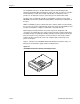
Introduction Chapter 1 Figure 1-2 Internal STT8000A with mounting brackets Features The STT8000A embodies Seagate's commitment to engineer reliable and durable tape drive products. Key features of the drive are as follows: • Two Internal form factors for installation in 5.25-inch half-high or 3.
Chapter 1 Introduction Typical system configurations The Enhanced IDE standard supports up to four ATAPI peripherals: two devices on the primary port and two devices on the secondary port. Of the two devices, one must be slave to the other, which is the master. Figure 1-3 shows sample configurations for two ATAPI systems.
Introduction Chapter 1 Instead, the write-read heads are logically or mechanically switched to a different position on the tape and another track is written or read in the reverse direction. That is, the drive first records track 1 in one direction and when the end of the tape is reached, the head is moved and the direction of tape motion is reversed to record track 2. This serpentine process continues until the entire tape is recorded.
Chapter 1 Introduction About this manual The remaining chapters and the appendices in this manual are briefly described in the following table. A glossary of terms is also included. Chapter Page 6 Title Description 2 Specifications Contains physical, performance, environmental, reliability, power, and minicartridge specification tables. 3 Installation Provides cautions, unpacking tips, inspection information, installation/connection instructions, mounting dimensions, and connector pinouts.
Specifications Chapter 2 Specifications 2 Overview The STT8000A provides exceptional reliability in storing large amounts of computer data.
Chapter 2 Specifications Figure 2-1 STT8000A (3.5-Inch mount) general dimensions 4.00 in (101.6 mm) 6.19 in (157.2 mm) 0.157 in (4 mm) 4.00 in (101.6 mm) 1.00 in (25.4 mm) Figure 2-2 STT8000A (5.25-Inch mount) general dimensions 0.86" (21.8mm) 5.49" (139.4mm) 5.76" (146.4mm) 0.20" (5.0mm) 5.87" (149.0mm) DRIVE ACTIVE (GREEN) Page 8 1.685" (42.
Specifications Chapter 2 Power specifications The following table lists the power specifications for the STT8000A. (Power specifications are measured at the tape drive power connector and are nominal values.) Specification Measurement DC Voltage +12 VDC +5 VDC Voltage Tolerance ± 10% ± 5% Operational Current 2.0 amps 1.0 amp Standby Current 0.2 amp 0.6 amp Peak 2.2 amps max.
Chapter 2 Specifications Performance specifications The following table lists the performance specifications for the STT8000A. Feature Page 10 Specification Capacity 4.0 gigabytes—900Oe 740' Travan cartridge (uncompressed) 8.0 gigabytes—900Oe 740’ Travan cartridge (compressed) Effective backup rate 30 Mbytes/min typical native; 45 Mbytes/min typ.
Specifications Chapter 2 Environmental requirements The following table lists the environmental specifications for the STT8000A. The drive may be mounted either vertically or horizontally. Specification Operational Non-operational Temperature +41° to +113° F1 (+ 5° to + 45° C) –40° to +149oF2 (–40° to + 65oC) Thermal gradient 1° C per minute (no condensation) 20° C per hour Relative humidity 20% to 80% non-condensing1 5% to 95% non-condensing2 Maximum wet bulb temperature 78.
Chapter 2 Specifications Reliability The STT8000A is designed for maximum reliability and data integrity. The following table summarizes the reliability specifications. Feature Specification Non-recoverable error rate < 1 in 10 bits Error recovery and control Reed-Solomon Error Correction Code techniques 15 Error monitoring and reporting (Error Log) Media pre-written Retry on read Data randomization Mean-Time-Between-Failures (MTBF) More than 200,000 hours Mean-Time-To-Repair (MTTR) Less than 0.
Specifications Chapter 2 Recommended tapes The STT8000A uses pre-formatted minicartridges. The following cartridges are recommended: Description Seagate Sony 3M/Imation Travan (740 ft) (QIC-3095) 4.0 GB capacity • 8.0 GB capacity with • data compression 8000TT — TR-4 Standard 900 Oe (400 ft) (QIC-3080) 1.6 GB capacity • 3.
Chapter 2 Specifications Regulatory compliance The STT8000A complies with the regulations listed in the following table. Agency Regulation CSA C22.2, No. 950-M89 TUV & IEC-RHEINLAND EN 60 950/IEC 950 UL 1950 Canadian Dept.
Installation Chapter 3 3 Installation Introduction This chapter explains how to install the STT8000A. The following paragraphs briefly outline the organization of this chapter. • The following section, Before you begin contains general information that you should read before you begin the installation. • Setting jumpers shows the master/slave jumpers and describes their uses. • Installing the drive explains how to mount the internal drive unit.
Chapter 3 Installation Setting jumpers Review the jumper settings to ensure that the jumpers are properly configured for your system. Figure 3-1 shows the location of the jumper block. Figure 3-2 shows the jumper block. Note: Record your jumper settings prior to installation. They are not visible after the drive has been installed. The default setting is Slave mode with a jumper over pin 3 and pin 4.
Installation Chapter 3 Installing the drive The internal drive can be installed in a one-half-inch high by 3.5-inch form factor drive bay or in an inch-high by 5.25-inch form factor (with mounting brackets). The drive can be installed in three different orientations: horizontally (LED to the left) and vertically (on either side). The following section provides directions for mounting the drive in either a 3.5-inch enclosure or in a 5.25-inch enclosure. 1.
Chapter 3 Installation 6. Secure the drive using the mounting screws. The threaded mounting brackets are designed for M3.0 metric screws. If you are mounting the drive in a 3.5-inch bay, use the screw supplied with the drive. Do not substitute other screws. Using longer screws may damage the drive. If slide rails are needed, use the plastic slide rails (supplied with the drive in some configurations). 7. Connect an available power cable to the power connector on the drive.
Installation Chapter 3 Figure 3-4 Mounting holes on internal drive (without mounting brackets) 0.2 in (5 mm) 3.7 in (94 mm) 0.315 in (8 mm) 2.758 in (70 mm) 3.543 in (90 mm) 6.2 in (159 mm) 2.382 in (60 mm) 1.220 in (31 mm) 0.984 in (25 mm) 4.0 in (102.6 mm) 0.157 in (4 mm) 1.0 in (25.4 mm) Figure 3-5 Mounting holes on internal drive (with mounting brackets) 0.4 in (10.2mm) 0.62 in (15.7mm) 0.86 in (21.8mm) .075 in (1.9mm) 2 PLACES 5.76 in (146.4mm) 3.12 in (79mm) 3.12 in (79,2mm) 5.
Chapter 3 Installation ATA-2 Interface pin assignments The STT8000A provides a standard ATA-2 connector. The pin assignments for this connector are listed in the following table for your reference.
Installation STT8000A Product Manual Chapter 3 Pin Assignment Description Source 24 –REQ Ground N/A 25 –I/O I/O Read Host 26 GND Ground N/A 27 IORDY I/O Ready Device 28 CSEL Cable Select Device 29 DMACK DMA Acknowledge Host 30 GND Ground N/A 31 INTRQ Interrupt Request Device 32 10CS16- 16-Bit I/O Device 33 DA1 Device Address Bit 1 Host 34 PDIAG Passed Diagnostics Device 35 DA0 Device Address Bit 0 Host 36 DA2 Device Address Bit 2 Host 37 CS0- Chip
Chapter 3 Installation Notes Page 22 STT8000A Product Manual
Drive operation and maintenance Chapter 4 Drive operation and maintenance 4 Introduction This chapter describes important operational procedures for the STT8000A. It covers the following topics: • Use of the front panel LED • Using cartridges • Loading revised firmware (updating flash EEPROM) • Drive maintenance and troubleshooting instructions. Front panel LED The front panel of the Travan drive (see Figure 4-1) contains the cartridge opening and one amber light-emitting diode (LED).
Chapter 4 Drive operation and maintenance Using Travan cartridges The minicartridges recommended for use with the STT8000A are listed in chapter 2. This section describes some operations using the cartridges. Loading and unloading cartridges Your tape drive has a flip-up door that covers the cartridge opening when a tape cartridge is not installed in the drive. Once a cartridge is inserted, it is held firmly in place by the drive's positive locking mechanism.
Drive operation and maintenance Chapter 4 Setting the write–protect switch Travan minicartridges feature a sliding write protect tab located in the upper left corner of the cartridge. You can set the tab to keep data from being written on the tape. Use this switch when you want to make sure that important data on the tape will not be overwritten. Figure 4-4 shows the cartridge with the switch in the non-protected (read/write) or unlocked position.
Chapter 4 Drive operation and maintenance Loading revised firmware via Seagate firmware cartridge The STT8000A uses flash EEPROM. Flash EEPROM enables you to download new firmware when revisions to firmware are released. Firmware revisions are released on specially encoded cartridges that are automatically recognized by these drives. These firmware revisions are available for qualified OEMs only from Seagate Technology, Inc. To load a firmware upgrade tape, follow these steps. 1.
Drive operation and maintenance Chapter 4 Care and maintenance of the drive and cartridges Minimal maintenance is needed to ensure that your STT8000A minicartridge drive operates at peak condition. This section explains how to care for tape cartridges and how to clean the drive head. Caring for tape cartridges Although minicartridge tape cartridges are ruggedly built, they must be handled with care to preserve the data that they contain.
Chapter 4 Drive operation and maintenance Cleaning the drive read/write head To maintain the tape drive, you should periodically clean the read/write head. No other periodic maintenance is required. For new cartridges, clean the head after two hours of tape movement. Thereafter the drive can be cleaned as per normal operations. Caution. Never clean the read/write head of the drive with anything other than a lint-free swab or an approved cleaning cartridge.
Drive operation and maintenance Chapter 4 Troubleshooting If you experience problems after you install the drive, take the following actions to try to solve the problems. 1. Make sure that all cable connections are secure. 2. Check the drive to be sure that the jumper settings are correct. If a power interruption occurs during a backup or restore operation, start over when the power is restored. If the drive appears to fail during a backup or restore operation, try the following steps: 1.
Chapter 4 Drive operation and maintenance Notes Page 30 STT8000A Product Manual
ATAPI Interface Chapter 5 ATAPI interface 5 Introduction The STT8000A provides an ATA Packet Interface (ATAPI) controller for communications between the host computer and the drive. The drive supports the QIC-157 standard interface. Note: Refer to the QIC-157 Standard for detailed information about the this interface. This chapter clarifies the use of several ATA-2 signals and ATAPI commands that are either vague or optional in the QIC-157 specification.
Chapter 5 ATAPI Interface ATA registers The following table lists the values for the registers during register initialization. Register POR RESET– (Hard Reset) ATA Reset (SRST Bit) ATAPI Soft Reset Read/Identify Device Cmds STATUS 00h 00h 00h 10h 41h (DRDY+ERR) ERROR 01h (No Error) 01h 01h 01h 04h (ABRT) Sector Count (ATAPI Intr. Reason) 01h 01h 01h 01h — Sector Num.
ATAPI Interface Chapter 5 Error Register The following layout represents the Error Register. 7 6 5 4 Sense Key [3..0] 3 2 1 0 MCR ABRT EOM ILI Bit(s) Mnemonic Description 7-4 Sense Key Set to indicate the reason for the CHECK bit being set in the Status Register. 3 MCR Media Change Request—Always 0. 2 ABRT Aborted Command—Set when an ATA or ATAPI command is aborted. 1 EOM End Of Media—The end of the current partition was detected.
Chapter 5 ATAPI Interface information. If you do not program this register correctly, the drive "hangs" in the BSY state. To correct this problem, reset operations. Supported ATA Commands The ATA commands are briefly described in the following paragraphs. Execute Drive Diags (90h) This command is executed regardless of the state of the DRV bit. The command causes an actual microprocessor reset (drive loses all logical position information).
ATAPI Interface Chapter 5 Set Features (EFh) If an unsupported feature is selected, the command is aborted. Otherwise, the indicated parameter is set.
Chapter 5 ATAPI Interface Issuing PIO and DMA transfer modes does not actually select these operations; however, issuing these modes selects the rate of either type of transfer, as selected by the DMA bit (bit 0) of the ATAPI Features register. ATAPI Identify Device (A1h) The protocol and timing of this command conforms to a standard ATA type command as defined in ATA-2. Note: This command is similar to the ATA Identify Device command except it uses a different op-code.
ATAPI Interface Chapter 5 Word Description Value Meaning 53 Field Validity 0002h Fields 54-58 not valid. Fields 64-70 valid 54-56 Current Cylinder/Heads/Sectors 0000h Unsupported 57-58 Current Capacity 0000h Unsupported 59 Reserved 0000h — 60-61 User Addressable Sectors 0000h Unsupported 62 Single Word DMA Mode 0407h Selected DMA mode 2 (Upper Byte), DMA modes 2,1,0 Supported. 63 Multi Word DMA Mode 0407h Selected DMA mode 2 (Upper Byte) DMA modes 2, 1, 0 supported.
Chapter 5 ATAPI Interface ATAPI interface The following table lists the ATAPI interface commands for the drive. In this table, DSC restrictive means that the host should wait for DSC to be set before issuing the command for minimum IDE bus overhead. Note that all ATAPI commands are 12 bytes in length. The command descriptions show only the first 6 or 10 bytes of these commands, even though the commands are actually 12 bytes long. Note.
ATAPI Interface Chapter 5 Erase command Bit=> 7 6 5 4 3 2 1 0 Byte 0 Operation code (19h) 1 Reserved 2 Reserved 3 Reserved 4 Reserved 5 Reserved 1 (Long) The Erase command is only accepted when the drive is ready and located at either BOP 0/1 or EOD. Erase at BOP causes the drive to write a Control/Filler Frame at the beginning of the current partition, followed by an EOD pattern. (The Use Count field of the Control Frame is incremented from its previous value).
Chapter 5 ATAPI Interface Inquiry command Bit 7 6 5 4 3 2 1 0 Byte 0 Operation code (12h) 1 Reserved 2 Reserved 3 Reserved 4-7 Allocation Length 8-15 Vendor ID (8 ASCII characters) ASCII “Seagate “ 16-31 Product ID (16 ASCII characters ASCII “STT8000A “ The INQUIRY command is always accepted, regardless of the state of the DSC bit. The command does not modify the status of DSC. The INQUIRY command returns the lesser of 36 bytes or the Allocation Length parameter of information.
ATAPI Interface Chapter 5 Load/Unload command Bit 7 6 5 4 3 2 1 0 Re-Ten Load Byte 0 Operation code (1Bh) 1 Reserved 2 Reserved 3 Reserved 4 Reserved 5 Reserved LOAD (with or without Re-tension) is accepted any time a tape is present in the drive, (even if status indicates it is already loaded). This command includes implicit rewind and select partition 0 operations. The DSC bit is reset (0) after this command is accepted and is set (1) when the drive has initialized and is ready.
Chapter 5 ATAPI Interface Locate command Bit 7 6 5 4 3 2 1 0 CP Reserved Byte 0 Operation code (2Bh) 1 Reserved 2 3 4 Reserved (MSB) Logical Block Address 5 6 (LSB) 7 Reserved 8 Partition 9 Reserved If the Change Partition (CP) bit is set, the drive first changes to the specified partition, then attempts to locate before the specified logical block. (All addresses are interpreted as logical.
ATAPI Interface Chapter 5 Log Select command Bit 7 6 5 4 3 2 1 0 PCR Reserved Byte 0 Operation code (4Ch) 1 Reserved 2 01(PC) Reserved 3 Reserved 4 Reserved 5 Reserved 6 Reserved 7 (MSB) Parameter List Length 8 (LSB) 9 Reserved The PC (Page Control) field is 01, for current values. The Parameter List Length field specifies the number of data bytes to transfer. If the PCR bit is 1 and the Parameter List Length is 0, the error counters are all reset (0).
Chapter 5 ATAPI Interface Log Sense command Bit 7 6 5 4 3 2 1 0 Byte 0 Operation code (4Dh) 1 Reserved 2 01(PC) Page Code 3 Reserved 4 Reserved 5 (MSB) Parameter Pointer 6 7 (LSB) (MSB) Allocation Length 8 (LSB) 9 Reserved The PC (Page Control) field is 01, for current values. The Page Code field identifies which page of data is being requested. The Parameter Pointer field allows requested parameter data to begin from a specific parameter code.
ATAPI Interface Chapter 5 Error Counter Page (Read) The following table presents the Error Counter Page layout.
Chapter 5 ATAPI Interface Tape Capacity Page Code The following table presents the Tape Capacity Page layout.
ATAPI Interface Chapter 5 Mode Select command Bit 7 6 5 4 3 2 1 0 Byte 0 Operation code (15h) 1 Reserved 2 3 1 (PF) Reserved Reserved (MSB) Parameter List Length 4 (LSB) 5 Reserved The Mode Select command provides a means to change device parameters. The PF (Page Format) bit is 1, since the Mode Pages are in SCSI-2 format. The only changeable parameters are Speed Selection (in the Mode Parameter Header), and certain fields in Mode Page 2Bh (MFM mode).
Chapter 5 ATAPI Interface Mode Sense command Bit 7 6 5 4 3 2 1 0 Byte 0 Operation code (1Ah) 1 Reserved 2 3 DBD 00(PC) (MSB) Reserved Page Code Allocation Length 4 (LSB) 5 Reserved The PC (Page Control) field is 00, since only current values are reported. If DBD (Disable Block Descriptor) is set (1), then the Mode Block Descriptor is not included in the data returned to the host.
ATAPI Interface Chapter 5 Mode Parameter Header The following table describes the Mode Parameter header.
Chapter 5 ATAPI Interface Mode Medium Partition Page The following table describes the Mode Medium Partition Page layout.
ATAPI Interface Chapter 5 Mode Tape Parameters Page Byte Description Value Meaning 0 Page Code 2Bh Tape Parameters Page 1 Page Length 0Eh 14 Bytes of Information 2 Density in Kilo bits per inch NN Density can imply tape format 3 Reserved 00h — 4 Reserved (Format Fill Byte) 00h Not used, MFM mode is read only 5 BSEG 20h Number of Blocks per Segment (32) 6,7 SEGTRK NNNN Number of Segments per Track 8,9 TRKS NN Number of Tracks (per Tape) 10 MAXSECT 80h Max MFM Sector V
Chapter 5 ATAPI Interface Read command Bit 7 6 5 4 3 2 1 0 Byte 0 Operation code (08h) 1 2 3 Reserved (MSB) Transfer Length 4 5 1 (Fixed) (LSB) Reserved The Transfer Length specifies the number of fixed 512 byte blocks to be transferred. A transfer length of 0 indicates that no data is to be transferred but will initiate a read-ahead. The DSC bit is reset (0) after this command is accepted and is set (1) when at least 52 blocks in the buffer are available for the next READ command.
ATAPI Interface Chapter 5 Read Position command Bit 7 6 5 4 3 2 1 0 Byte 0 Operation code (34h) 1 Reserved 2 Reserved 3 Reserved 4 Reserved 5 Reserved 6 Reserved 7 Reserved 8 Reserved 9 Reserved The following table describes the Read Position layout.
Chapter 5 ATAPI Interface *These fields might appear to report the number of bytes/blocks in the buffer. However, this information is not guaranteed to be accurate. You should not rely on this information. The only position that is guaranteed is the host logical block position. The First and Last Block Locations both return the same host location, and Blocks and Bytes in Buffer are reported as 0.
ATAPI Interface Chapter 5 Request Sense command Bit 7 6 5 4 3 2 1 0 Byte 0 Operation code (03h) 1 Reserved 2 Reserved 3 Reserved 4 Allocation Length 5 Reserved An Allocation Length value of 20 will return all Request Sense data. The Request Sense command is always accepted, regardless of the state of the DSC bit, but the status is valid only when DSC or CHK (error) is set (1). If DSC and CHK are both reset (0), a non-error “null” status is returned.
Chapter 5 ATAPI Interface The following table describes the REQUEST SENSE layout.
ATAPI Interface Chapter 5 Rewind command Bit 7 6 5 4 3 2 1 0 Byte 0 Operation code (01h) 1 Reserved 2 Reserved 3 Reserved 4 Reserved 5 Reserved The Rewind command first ensures that all buffered write data has been transferred to the medium, then causes the device to position to BOP of the current partition. The DSC bit is reset (0) after this command is accepted and is set (1) when the drive is ready to write at BOP0 (or encountered a hardware error).
Chapter 5 ATAPI Interface Space command Bit 7 6 5 4 3 2 1 0 Byte 0 Operation code (11h) 1 2 3 Reserved Space Code (MSB) Count 4 5 (LSB) Reserved The only Space codes that are supported are 001b (Filemarks) and 011b (End of Data on Current Partition). For Space Filemarks, negative count (2s compliment) indicates Space Filemarks Reverse. The DSC bit is reset (0) after this command is accepted and is set (1) when the command is completed and the drive is ready.
ATAPI Interface Chapter 5 Test Unit Ready command Bit 7 6 5 4 3 2 1 0 Byte 0 Operation code (00h) 1 Reserved 2 Reserved 3 Reserved 4 Reserved 5 Reserved This command can be used to determine the readiness of the device to accept a media access command. It’s purpose is to indicate the cartridge state: no cartridge (or drive fault), cartridge becoming ready, or cartridge/drive ready.
Chapter 5 ATAPI Interface Write command Bit 7 6 5 4 3 2 1 0 Byte 0 Operation code (0Ah) 1 Reserved 1 2 3 Reserved (MSB) Transfer Length 4 5 1 (Fixed) (LSB) Reserved The Transfer Length specifies the number of fixed 512 byte blocks to be transferred. A transfer length of 0 indicates that no data is to be transferred but is used on some drives to put DSC into write buffer mode. The DSC bit is reset (0) after this command is accepted and all data has been transferred.
ATAPI Interface Chapter 5 Write Filemark command Bit 7 6 5 4 3 2 1 0 Byte 0 Operation code (10h) 1 Reserved 2 Reserved 3 Reserved 4 Reserved 5 Count Reserved After receiving this command, the device sets DSC (0) and returns completion status. Any data remaining in the buffer is then written to tape (flush/ synchronize), and if the count is 1, a Filemark is written. In any case, an EOD is then written.
Chapter 5 ATAPI Interface Write Buffer (download microcode) command Bit 7 6 5 4 3 2 1 0 Byte 0 Operation code (3Bh) 1 Reserved 101 (Mode) 2 Reserved 3 Reserved 4 Reserved 5 Reserved 6 7 (MSB) Transfer Length 8 9 (LSB) Reserved The Write Buffer command is intended only to provide a method for downloading new drive microcode (firmware) into Flash EPROM, so the only valid MODE is 101 (download microcode and save).
Tape format Chapter 6 6 Tape format Introduction The STT8000 ATAPI minicartridge drive conforms to the QIC-3095-MC recording format standard. This format is for streaming magnetic tape in a minicartridge that is to be used for information interchange among information processing systems, communication systems, and associated equipment. This chapter provides an overview of the tape format used by the STT8000 ATAPI minicartridge drive.
Chapter 6 Tape format Track numbering All even numbered tracks, and the Directory Track, are recorded in the forward direction (the direction from the BOT marker to the EOT marker). All odd numbered tracks are recorded in the reverse direction (the direction from the EOT marker to the BOT marker). All even numbered tracks are located below the Directory Track; all odd numbered tracks are above it. Track format Tracks are recorded sequentially beginning with track 0, then track 1, and so on.
Tape format Chapter 6 Figure 6-1 General track layout Frame N Frame N+1 Frame N+2 Frame N+3 Frame N+4 Frames are numbered indirectly using the 26 most significant bits of the Physical Block Address. Frame operation is controlled by the drive and generally invisible to the host. Frames are used primarily as a means to control the error correction operations. Frames can be overwritten with new data frames or an end-of-data (EOD) frame. Append operations can only begin at EOD.
Chapter 6 Tape format Blocks Information in the Block Control byte determines the type of block being recorded except for ECC blocks which are recognized by their block numbers. Also, information about the number of user data bytes available in each data block is recorded in the Block Control byte of the block. The Data Field of the blocks always contain 512 bytes. However, the number of valid data bytes in the block may be less than 512.
Tape format Chapter 6 Write equalization The drive uses the technique of write equalization. RLL encoding has a 4:1 ratio in the minimum and maximum spacing between flux transitions. Write equalization inserts short pulses in the write current to break up the long spacing intervals. These pulses are too short to be detected in the read process but result in significant improvement in read-back resolution.
Chapter 6 Tape format Notes Page 68 STT8000A Product Manual
Theory of operations Chapter 7 7 Theory of operations Overview The STT8000 ATAPI minicartridge drive is based on proven Seagate designs, Seagate firmware, and the latest technology. This drive uses second generation, custom LSIs for efficient circuit layout and increased reliability with low power consumption. The drive also uses flash EEPROM devices for easy firmware upgrades. This chapter describes the drive in more detail and explains implementation specific information.
Chapter 7 Theory of operations The following table shows clock frequencies used by the STT8000 drive VCO Frequencies—All Derived from System Clock (42 MHz Crystal Oscillator) Fundamental Frequency 28 MHz 28 MHz 28 MHz 24.89 MHz Channel Frequency 9.33 MHz 7.00 MHz 4.667 MHz 3.
Theory of operations Chapter 7 Control circuits The control logic module shown in Figure 7-1 includes a buffer manager to handle data movement between the controller, the buffer, and the tape formatter. This module also includes logic to perform ECC and CRC generation and testing, WRITE/READ data formatting, head stepper control, and drive motor control. The microprocessor directs all functions performed by the control logic.
Chapter 7 Theory of operations the position of the SAFE indicator on the cartridge and disables writing of writeprotected (SAFE) cartridges. The Head-Position Sensor is an electro-optical assembly (LED and photo-transistor) to determine the approximate head position.
Glossary Appendix A Glossary A ATA Packet Interface—The interface providing for communications between the host computer and the drive (standard QIC-157). Azimuth—The angular deviation, in minutes of arc, of the mean flux transition line from the line normal to the tape reference edge. Backup—Copy of a file or collection of files on fixed disk, diskette, or tape. Ensures against data loss. Beginning of Media (BOM)—Equal to the physical beginning of the tape.
Appendix A Glossary Dew—Collection of moisture in a tape drive. Directory track—The track at the centerline of the tape, identified as track 254 by its Track ID frame. Disc Drive—A peripheral storage device that rotates the disk, writes data onto it, and reads data from it as instructed by a program. ECC—(Error Correction Code) Special drive generated information that can be used to correct bad blocks. ECC block—A block containing drive-generated ECC data in its data field and part of control field.
Glossary Appendix A Randomizing—A re-coding of data symbols before they are written to tape in order to provide a consistently uniform RF envelope level. RLL (Run Length Limited)—A data encoding method where data bits are encoded so that certain constraints are met with regard to the maximum and minimum distances between flux transitions. Serpentine—A recording method in which tracks are laid down sequentially, and the tape is not rewound at the end of a track.
Appendix A Glossary Notes Page 76 STT8000A Product Manual
Acronyms and Measurements Appendix B Acronyms and measurements B Acronyms and abbreviations STT8000A Product Manual Acronym Meaning ANSI American National Standards Institute BIOS Basic Input Output System BOM Beginning of Media BOT Beginning Of Tape BPI Bits Per Inch CD Compact Disc CMOS Complementary Metal-Oxide Semiconductor CSA Canadian Standard Association DMA Direct Memory Access ECC Error Correction Code ECMA European Computer Manufacturers Association EEPROM Electronic
Appendix B Page 78 Acronyms and Measurements Acronym Meaning LSI Large Scale Integration MTBF Mean Times Between Failures MTTR Mean Time To Repair OEM Original Equipment Manufacturer PCB Printed Circuit Board QIC Quarter Inch Cartridge Drive Standards, Incorporated RAM Random Access Memory RLL Run Length Limited SCSI Small Computer System Interface UL Underwriters' Laboratories, Inc.
Acronyms and Measurements Appendix B Units of measurement Measure Meaning A Amp C Celsius or Centigrade cm centimeter dBa decibels, A-weighted sound power reference one picowatt F Fahrenheit ft foot or feet g acceleration of a free-falling body; equal to 32.17 feet per second2 Gbyte gigabyte Hz Hertz in.
Appendix B Page 80 Acronyms and Measurements STT8000A Product Manual