Product Manual SV35 Series SATA ST3500641SV ST3250824SV ST3160812SV 100415208 Rev.
Revision history Revision Rev. A Rev. B Rev. C Date 04/25/06 08/23/07 10/01/07 Sheets affected or comments Initial release. 1. 4, 8, 11 and 18. Copyright © 2006-2007 Seagate Technology LLC. All rights reserved. Printed in U.S.A. Publication number: 100415208, Rev. C October 2007 Seagate, Seagate Technology and the Wave logo are registered trademarks of Seagate Technology LLC in the United States and/or other countries.
Contents 1.0 Introduction. . . . . . . . . . . . . . . . . . . . . . . . . . . . . . . . . . . . . . . . . . . . . . . . . . . . . . . . . . . . . . . . . . . 1 1.1 About the Serial ATA interface . . . . . . . . . . . . . . . . . . . . . . . . . . . . . . . . . . . . . . . . . . . . . . 2 2.0 Drive specifications . . . . . . . . . . . . . . . . . . . . . . . . . . . . . . . . . . . . . . . . . . . . . . . . . . . . . . . . . . . . 3 2.1 Specification summaries . . . . . . . . . . . . . . . . . . . . . .
ii SV35 Series SATA Product Manual, Rev.
List of Figures Figure 1. Figure 2. Figure 3. Figure 4. Figure 5. Figure 6. Typical 5V startup and operation current profile . . . . . . . . . . . . . . . . . . . . . . . . . . . . . . . . . . . Typical 12V startup and operation current profile . . . . . . . . . . . . . . . . . . . . . . . . . . . . . . . . . . Breather filter hole location . . . . . . . . . . . . . . . . . . . . . . . . . . . . . . . . . . . . . . . . . . . . . . . . . . . Serial ATA jumper block and connectors . . . . . . . . . . . . . .
1.0 Introduction This manual describes the functional, mechanical and interface specifications for the following Seagate SV35 Series SATA model drives: • ST3500641SV • ST3250824SV • ST3160812SV These drives provide the following key features: • Specifically designed for surveilance DVRs. • Optimized power for surveillance systems--spinup limited to a maximum to 2.0 amps. • Seek profile optimized for surveillance performance and power consumption. • 7,200 RPM spindle speed. • 16 Mbyte buffer: ST3500641SV.
1.1 About the Serial ATA interface The Serial ATA interface provides several advantages over the traditional (parallel) ATA interface. The primary advantages include: • Easy installation and configuration with true plug-and-play connectivity. It is not necessary to set any jumpers or other configuration options. • Thinner and more flexible cabling for improved enclosure airflow and ease of installation. • Scalability to higher performance levels.
2.0 Drive specifications Unless otherwise noted, all specifications are measured under ambient conditions, at 25°C, and nominal power. For convenience, the phrases the drive and this drive are used throughout this manual to indicate the following models: ST3500641SV ST3250824SV ST3160812SV 2.1 Specification summaries The specifications listed in tables 1 and 2 are for quick reference. For details on specification measurement or definition, see the appropriate section of this manual.
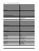
Table 1: Drive specifications for 500 Gbyte models Drive specification ST3500641SV Formatted Gbytes (512 bytes/sector)* 500 Guaranteed sectors 976,773,168 Bytes per sector 512 Default sectors per track 63 Default read/write heads 16 Default cylinders 16,383 Recording density in BPI (kbits/inch max) 790.1 Track density TPI (ktracks/inch avg) 124.5 2 Areal density (Gbits/inch avg) 97.96 Spindle speed (RPM) 7,200 Internal data transfer rate (Mbits/sec max) 815.
Table 1: Drive specifications for 500 Gbyte models Drive specification ST3500641SV Altitude, nonoperating (meters below mean sea level, max) –60.96 m to 12,192 m (–200 ft to 40,000+ ft) Shock, operating (max at 2 msec) 63 Gs Shock, nonoperating (max at 2 msec) 300 Gs Vibration, operating 5-22 Hz: +/-0.25”, Displacement limited 22-350 Hz: 0.5 Gs 350-500 Hz: 0.25 Gs Vibration, nonoperating 5-22 Hz: +/-0.25”, Displacement limited 23-350 Hz: 5.0 Gs 351-500 Hz: 1.
Table 2: Drive specifications for 250 Gbyte models Drive specification ST3250824SV Formatted Gbytes (512 bytes/sector)* 250 Guaranteed sectors 488,397,168 Bytes per sector 512 Default sectors per track 63 Default read/write heads 16 Default cylinders 16,383 Recording density in BPI (kbits/inch max) 790.1 Track density TPI (ktracks/inch avg) 124.5 2 Areal density (Gbits/inch avg) 97.69 Spindle speed (RPM) 7,200 Internal data transfer rate (Mbits/sec max) 867.
Table 2: Drive specifications for 250 Gbyte models Drive specification ST3250824SV Altitude, nonoperating (meters below mean sea level, max) –60.96 m to 12,192 m (–200 ft to 40,000+ ft) Shock, operating (max at 2 msec) 63 Gs Shock, nonoperating (max at 2 msec) 350 Gs Vibration, operating 5-22 Hz: +/-0.25”, Displacement limited 22-350 Hz: 0.5 Gs 350-500 Hz: 0.25 Gs Vibration, nonoperating 5-22 Hz: +/-0.25”, Displacement limited 22-350 Hz: 5.0 Gs 350-500 Hz: 1.
Table 3: Drive specifications for 160 Gbyte models Drive specification ST3160812SV Formatted Gbytes (512 bytes/sector)* 160 Guaranteed sectors 312,581,808 Bytes per sector 512 Default sectors per track 63 Default read/write heads 16 Default cylinders 16,383 Recording density in BPI (kbits/inch max) 840.0 Track density TPI (ktracks/inch avg) 141.5 2 Areal density (Gbits/inch avg) 119.0 Spindle speed (RPM) 7,200 Internal data transfer rate (Mbits/sec max) 867.
Table 3: Drive specifications for 160 Gbyte models Drive specification ST3160812SV Altitude, nonoperating (meters below mean sea level, max) –60.96 m to 12,192 m (–200 ft to 40,000+ ft) Shock, operating (max at 2 msec) 63 Gs Shock, nonoperating (max at 2 msec) 350 Gs Vibration, operating 5-22 Hz: 0.25 Gs, Limited displacement 22-350 Hz: 0.5 Gs 350-500 Hz: 0.25 Gs Vibration, nonoperating 5-22 Hz: 0.25 Gs, Limited displacement 23-350 Hz: 5.0 Gs 351-500 Hz: 1.
2.2 Formatted capacity Model Formatted capacity* Guaranteed sectors Bytes per sector ST3500641SV 500 Gbytes 976,773,168 512 ST3250824SV 250 Gbytes 488,397,168 512 ST3160812SV 160 Gbytes 312,581,808 512 *One Gbyte equals one billion bytes when referring to hard drive capacity. Accessible capacity may vary depending on operating environment and formatting. 2.2.
2.4 Recording and interface technology Interface ATA Recording method 16/17 EPRML Recording density KBPI (kbits/inch max) ST3500641SV and ST3250824SV 790.1 ST3160812SV 840.0 Track density KTPI (ktracks/inch max) ST3500641SV and ST3250824SV 124.5 ST3160812SV 141.5 Areal density (Gbits/inch2 max) ST3500641SV and ST3250824SV 97.69 ST3160812SV 119.0 Spindle speed (RPM) (± 0.2%) 7,200 Internal data-transfer rate (Mbits/sec max) ST3500641SV 815.2 ST3250824SV and ST3160812SV 867.
2.5 Physical characteristics Drive specification Maximum height (mm) (inches) 26.1 1.028 Maximum width (mm) (inches) 101.6 4.000 +/- 0.010 Maximum length (mm) (inches) 146.99 5.787 Maximum weight ST3500641SV ST3250824SV ST3160812SV 2.6 710 grams (1.57 lbs) 580 grams (1.28 lbs) Seek time Seek measurements are taken with nominal power at 25°C ambient temperature. All times are measured using drive diagnostics.
2.7 Start/stop times Power-on to Ready (sec) 16 Standby to Ready (sec) 16 (max) Ready to spindle stop (sec) 10 (max) 2.8 Power specifications The drive receives DC power (+5V and +12V) through a native SATA power connector. See Figure 5 on page 25. 2.8.1 Power consumption Power requirements for the drives are listed in the table on page 9. Typical power measurements are based on an average of drives tested, under nominal conditions, using 5.0V and 12.0V input voltage at 25°C ambient temperature.
Table 4: DC power requirements Power dissipation (typical) Example: ST3500641SV Average (watts, 25° C) 5V typ amps 12V typ amps Spinup — — 2.0 (peak) Idle 6.9 0.353 0.519 Operating (DVR Storage Profile) 8.44 0.478 0.50 Seeking 12.60 0.613 0.795 Standby 0.80 0.106 0.023 Sleep 0.80 0.106 0.023 2.8.1.
2.8.2 Conducted noise Input noise ripple is measured at the host system power supply across an equivalent 80-ohm resistive load on the +12 volt line or an equivalent 15-ohm resistive load on the +5 volt line. • Using 12-volt power, the drive is expected to operate with a maximum of 120 mV peak-to-peak square-wave injected noise at up to 10 MHz. • Using 5-volt power, the drive is expected to operate with a maximum of 100 mV peak-to-peak square-wave injected noise at up to 10 MHz. Note.
Each time the drive performs an Active function (read, write or seek), the standby timer is reinitialized and begins counting down from its specified delay times to zero. If the standby timer reaches zero before any drive activity is required, the drive makes a transition to Standby mode. In both Idle and Standby mode, the drive accepts all commands and returns to Active mode when disc access is necessary. 2.9 Environmental specifications 2.9.
2.9.5 Shock All shock specifications assume that the drive is mounted securely with the input shock applied at the drive mounting screws. Shock may be applied in the X, Y or Z axis. 2.9.5.1 Operating shock These drives comply with the performance levels specified in this document when subjected to a maximum operating shock of 63 Gs based on half-sine shock pulses of 2 msec. Shocks should not be repeated more than two times per second. 2.9.5.
2.10 Acoustics Drive acoustics are measured as overall A-weighted acoustic sound power levels (no pure tones). All measurements are consistent with ISO document 7779. Sound power measurements are taken under essentially free-field conditions over a reflecting plane. For all tests, the drive is oriented with the cover facing upward. Note. For seek mode tests, the drive is placed in seek mode only. The number of seeks per second is defined by the following equation: (Number of seeks per second = 0.
2.12 Reliability Nonrecoverable read errors 1 per 1014 bits read, max Annualized Failure Rate (AFR) <1% (nominal power, 8760 power on hours, 25°C ambient temperature) Contact start-stop cycles 50,000 cycles (at nominal voltage and temperature, with 60 cycles per hour and a 50% duty cycle) Preventive maintenance None required 2.13 Agency certification 2.13.1 Safety certification The drives are recognized in accordance with UL 1950 and CSA C22.
Australian C-Tick (N176) If these models have the C-Tick marking, they comply with the Australia/New Zealand Standard AS/NZS3548 1995 and meet the Electromagnetic Compatibility (EMC) Framework requirements of the Australian Communication Authority (ACA). 2.13.3 FCC verification These drives are intended to be contained solely within a personal computer or similar enclosure (not attached as an external device).
2.14 Environmental protection Seagate designs its products to meet environmental protection requirements worldwide, including regulations restricting certain chemical substances. 2.14.1 European Union Restriction of Hazardous Substances (RoHS) The European Union Restriction of Hazardous Substances (RoHS) Directive restricts the presence of chemical substances, including Lead (Pb), in electronic products effective July 2006.
22 SV35 Series SATA Product Manual, Rev.
3.0 Configuring and mounting the drive This section contains the specifications and instructions for configuring and mounting the drive. 3.1 Handling and static-discharge precautions After unpacking, and before installation, the drive may be exposed to potential handling and electrostatic discharge (ESD) hazards. Observe the following standard handling and static-discharge precautions: Caution: • Keep the drive in the electrostatic discharge (ESG) bag until you are ready for installation.
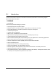
3.2 Breather filter hole precautions This section contains information regarding the precautions to take with the breather filter hole in Seagate hard disc drives. Take the proper precautions to ensure full functionality and to prevent possible damage to the drive. Breather hole Do not cover or seal this hole. Figure 3 Breather filter hole location Caution: Do not cover, seal, or insert any object into this hole.
3.3 Configuring the drive Each drive on the Serial ATA interface connects in a point-to-point configuration with the Serial ATA host adapter. There is no master/slave relationship because each drive is considered a master in a point-to-point relationships. If two drives are attached on one Serial ATA host adapter, the host operating system views the two devices as if they were both “masters” on two separate ports. This means both drives behave as if they are Device 0 (master) devices.
3.5 Drive mounting You can mount the drive in any orientation using four screws in the side-mounting holes or four screws in the bottom-mounting holes. See Figure 6 on page 26 for drive mounting dimensions. Follow these important mounting precautions when mounting the drive: • Allow a minimum clearance of 0.030 inches (0.76 mm) around the entire perimeter of the drive for cooling. • Use only 6-32 UNC mounting screws. • The screws should be inserted no more than 0.150 inch (3.
4.0 Serial ATA (SATA) interface These drives use the industry-standard Serial ATA interface that supports FIS data transfers. It supports ATA programmed input/output (PIO) modes 0–4; multiword DMA modes 0–2, and Ultra DMA modes 0–6. For detailed information about the Serial ATA interface, refer to the “Serial ATA: High Speed Serialized AT Attachment” specification. 4.
4.2 Serial ATA device plug connector pin definitions Table 6 summarizes the signals on the Serial ATA interface and power connectors.. Table 6: Segment Signal Serial ATA connector pin definitions Pin Function Definition S1 Ground 2nd mate S2 A+ Differential signal pair A from Phy S3 A- S4 Ground 2nd mate S5 B- Differential signal pair B from Phy S6 B+ S7 Ground 2nd mate Key and spacing separate signal and power segments Power P1 V33 3.3V power P2 V33 3.3V power P3 V33 3.
case, the mating sequences are: • the ground pins P4 and P12. • the pre-charge power pins and the other ground pins. • the signal pins and the rest of the power pins. 3. There are three power pins for each voltage. One pin from each voltage is used for pre-charge when installed in a blind-mate backplane configuration. 4. All used voltage pins (Vx) must be terminated. SV35 Series SATA Product Manual, Rev.
4.3 Supported ATA commands The following table lists Serial ATA standard commands that the drive supports. For a detailed description of the ATA commands, refer to the Serial ATA: High Speed Serialized AT Attachment specification. See “S.M.A.R.T. commands” on page 38.for details and subcommands used in the S.M.A.R.T. implementation.
Command name Command code (in hex) Read Sectors 20H Read Sectors Extended 24H Read Sectors Without Retries 21H Read Verify Sectors 40H Read Verify Sectors Extended 42H Read Verify Sectors Without Retries 41H Recalibrate 10H Security Disable Password F6H Security Erase Prepare F3H Security Erase Unit F4H Security Freeze F5H Security Set Password F1H Security Unlock F2H Seek 70H Set Features EFH Set Max Address F9H Note: Individual Set Max Address commands are identified by t
Command name Command code (in hex) S.M.A.R.T. Read Log Sector B0H / D5H S.M.A.R.T. Return Status B0H / DAH S.M.A.R.T. Save Attribute Values B0H / D3H S.M.A.R.T.
4.3.1 Identify Device command The Identify Device command (command code ECH) transfers information about the drive to the host following power up. The data is organized as a single 512-byte block of data, whose contents are shown in Table 7 on page 30. All reserved bits or words should be set to zero. Parameters listed with an “x” are drive-specific or vary with the state of the drive. See Section 2.0 on page 3 for default parameter settings.
Word Description Value 53 Words 54–58, 64–70 and 88 are valid 0007H 54 Number of current logical cylinders xxxxH 55 Number of current logical heads xxxxH 56 Number of current logical sectors per logical track xxxxH 57–58 Current capacity in sectors xxxxH 59 Number of sectors transferred during a Read Multiple or Write Multiple command xxxxH 60–61 Total number of user-addressable LBA sectors available (see Section 2.
Word Description Value 83 Command sets supported 7C03H 84 Command sets support extension 4003H 85 Command sets enabled 30xxH 86 Command sets enabled 0001H 87 Command sets enable extension 4000H 88 Ultra DMA support and current mode (see note following this table) xx3FH 89 Security erase time 0000H 90 Enhanced security erase time 0000H 92 Master password revision code FFFEH 93 Hardware reset value (see description following this table) xxxxH 95–99 ATA-reserved 0000H 100–10
36 10 Multiword DMA mode 2 is currently active. Bit Word 88 0 Ultra DMA mode 0 is supported. 1 Ultra DMA mode 1 is supported. 2 Ultra DMA mode 2 is supported. 3 Ultra DMA mode 3 is supported. 4 Ultra DMA mode 4 is supported. 5 Ultra DMA mode 5 is supported. 6 Ultra DMA mode 6 is supported. 8 Ultra DMA mode 0 is currently active. 9 Ultra DMA mode 1 is currently active. 10 Ultra DMA mode 2 is currently active. 11 Ultra DMA mode 3 is currently active.
4.3.2 Set Features command This command controls the implementation of various features that the drive supports. When the drive receives this command, it sets BSY, checks the contents of the Features register, clears BSY and generates an interrupt. If the value in the register does not represent a feature that the drive supports, the command is aborted. Power-on default has the read look-ahead and write caching features enabled.
Table 8: F1H Note. Set Features command values Report full capacity available At power-on, or after a hardware or software reset, the default values of the features are as indicated above. 4.3.3 S.M.A.R.T. commands S.M.A.R.T. provides near-term failure prediction for disc drives. When S.M.A.R.T. is enabled, the drive monitors predetermined drive attributes that are susceptible to degradation over time. If self-monitoring determines that a failure is likely, S.M.A.R.T.
4.3.4 Streaming feature set support The Streaming feature set is an optional feature set that allows a host to request delivery of data from a contiguous logical block address range within an allotted time. This places a higher priority on time to access the data than the integrity of the data. Streaming feature set commands only support 48-bit, LBA-mode-only addressing.
The streaming commands may access any user LBA on a device. These commands may be interspersed with non-streaming commands, but there may be an impact on performance due to the unknown time required to complete the non-streaming commands. The streaming commands should be issued using a specified minimum number of sectors transferred per command, as specified in word 95 of the IDENTIFY DEVICE response.
4.3.4.2.1 Configure Stream (51h) The Configure Stream command specifies the default CCTL (Command Completion Time Limit) for streaming commands, and informs the drive of the Allocation Unit size and alignment.
4.3.4.2.2 Read Stream DMA (2Ah) Protocol: DMA In This command reads from 1 to 65536 sectors as specified in the Sector Count register. A value of 0000h in the Sector Count register requests 65536 sectors. The RC bit indicates that the drive operate in a continuous read mode for the READ STREAM command. When RC is set to 0, the drive shall operate in normal streaming read mode.
If the value is 0, the drive shall use the Default Command Completion Time Limit supplied with the most recent previous CONFIGURE STREAM command for this Stream type (Read or Write). If the Default Command Completion Time Limit is 0, or no previous Configure Stream command was defined for this Stream type, the result is vendor specific. The time is measured from the write of the command register to the final INTRQ for command completion.
CCTO (Command Completion Time Out) 1 This bit shall be set to 1 if a Command Completion Time Out error has occurred. SECTOR COUNT REGISTER FIELD DESCRIPTIONS LBA Low/Mid/High The address of the first uncorrectable error. DEVICE REGISTER FIELD DESCRIPTIONS DEV This field indicates the selected device. STATUS REGISTER FIELD DESCRIPTIONS BSY 0 This bit shall be set to 0 indicating command completion.
4.3.4.3 Write Stream DMA (3Ah) Protocol: DMA Out The Write Stream DMA command allows the host to write data using the DMA data transfer protocol. This command allows for the host to specify to the device that additional actions need to be performed prior to the completion of the command if the required bits are set. If the Write Continuous bit is set to 1, the device shall attempt to not stop execution of the command due to errors.
F 1 This bit specifies that all data for the specified stream shall be flushed to the media before command complete is reported. CCTL (Command Completion Time Limit) The time allowed for the current command to complete.
IDNF 1 This bit shall be set to 1 if a user-accessible address could not be found. IDNF shall be set to 1 if an address outside of the range of user-accessible addresses is requested if command aborted is not returned. ABRT 1 This bit shall be set to 1 if this command is not supported. ABRT may be set to 1 if the device is not able to complete the action requested by the command. ABRT shall be set to 1 if an address outside of the range of user-accessible addresses is requested if IDNF is not set to 1.
If write caching is allowed, the actuator could be busy servicing a cached write at virtually any time. The implication is that a timeout on a read command could actually be due to a cached write.
5.0 Seagate Technology support services Internet For information regarding Seagate products and services, visit www.seagate.com. Worldwide support is available 24 hours daily by email for your questions. Presales Support: Presales@Seagate.com Technical Support: DiscSupport@Seagate.com Warranty Support: http://www.seagate.com/support/service/index.html mySeagate my.seagate.com is the industry's first Web portal designed specifically for OEMs and distributors.
Customer Service Operations Warranty Service Seagate offers worldwide customer support for Seagate products. Seagate distributors, OEMs and other direct customers should contact their Seagate Customer Service Operations (CSO) representative for warrantyrelated issues. Resellers or end users of drive products should contact their place of purchase or Seagate warranty service for assistance. Have your serial number and model or part number available.
Index Numerics 3D Defense System 1 A ACA 20 acceleration 17 acoustics 7, 9, 18 Active 15 Active mode 15 actuator arm 13 AFR 19 Agency certification 19 altitude 16 Altitude, nonoperating 5, 7, 9 Altitude, operating 4, 6, 8 Ambient temperature 4, 6, 8, 16 ambient temperature 12, 13 Annualized Failure Rate (AFR) 5, 7, 9, 19 Areal density 4, 6, 8 areal density 11 ATA commands 30 ATA data-transfer modes supported 4, 6, 8 Australia/New Zealand Standard AS/NZS3548 1995 20 Australian Communication Authority (ACA)
Execute Device Diagnostics 30 L F latency 4, 6, 8, 12 latency time 13 LBA mode 10 Length 4, 6, 8 logical geometry 10 FCC verification 20 features 1 Federal Communications Commission 20 Flush Cache 30 Flush Cache Extended 30 Format Track 30 Formatted capacity 10 Formatted Gbytes 4, 6, 8 G Gbytes 10 geometry 10 gradient 4, 6, 8 Gs 17 Guaranteed sectors 4, 6, 8, 10 guaranteed sectors 10 H Handling precautions 23 heads 4, 6, 8, 10 Height 4, 6, 8 height 12 humidity 4, 6, 8, 16 I I/O data-transfer rate 4,
random seeks 13 Read Buffer 30 Read DMA 30 Read DMA Extended 30 Read DMA without Retries 30 read errors 5, 7, 9, 19 Read Log Ext 30 Read Multiple 1, 30 Read Multiple Extended 30 Read Native Max Address 30 Read Native Max Address Extended 30 Read Sectors 31 Read Sectors Extended 31 Read Sectors Without Retries 31 Read Verify Sectors 31 Read Verify Sectors Extended 31 Read Verify Sectors Without Retries 31 read/write actuator arm 13 Read/write heads 10 Ready to spindle stop 13 Recalibrate 31 Recording density
TPI 4, 6, 8 Track density 4, 6, 8 track density 11 Track-to-track 12 Track-to-track seek time 4, 6, 8, 12 Tunneling Magnetoresistive (TMR) heads 1 TUV North America 19 U UL 1950 19 V Vibration 17 Vibration, nonoperating 5, 7, 9 Vibration, operating 5, 7, 9 voltage 13 Voltage dips, interrupts 18 Voltage tolerance 4, 6, 8, 15 W Weight 4, 6, 8 Wet bulb temperature 4, 6, 8 wet bulb temperature 16 Width 4, 6, 8 Write Buffer 32 Write DMA 32 Write DMA Extended 32 Write DMA FUA Extended 32 Write DMA Without Retr
Seagate Technology LLC 920 Disc Drive, Scotts Valley, California 95066-4544, USA Publication Number: 100415208, Rev. C, Printed in U.S.A.