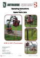
Operating Instructions and Spare Parts Lists MINI & MIDI Postmaster Autoguide Equipment Stockley Road Heddington Nr. Calne Wiltshire SN11 0PS England Tel: +44 (0) 1380 850885 Fax: +44 (0) 1380 850010 Website: www.autoguide.co.uk Issue 2.
These instructions give safety and operations information regarding the use of a Digger Mounted Postmaster supplied by Autoguide Equipment. They contain the relevant information for products: Product Code Description Force (kN) 47315 Mini Postmaster 50 48298 Midi Postmaster 60 To ensure optimum results when operating this machine it is very important to read this manual carefully, the information will prepare you to do a better, safer job.
CONTENTS Information ................................................................................................................................... 3 Safety Instructions .................................................................................................................... 3 Daily Check Items ..................................................................................................................... 4 Postmaster Specification .......................................................
INFORMATION Your Postmaster has been individually built with great emphasis on quality, strength and simplicity of design and with routine care will give many years of trouble free operation. The following instructions have been written to cover the use and maintenance of the machine. Care should be taken to ensure that you are referring to the correct section of your machine before carrying out any adjustments, or when ordering spare parts.
Daily Check Items 1. Check the unit is properly and securely attached to the crane/excavator unit. 2. Checks that all nuts and bolts are secure, mounting pins are properly retained, and all safety shields are in place. (All nuts and bolts should be checked after the first 10 hours of operation.) 3. Check the condition and security of the safety webbing. 4. Lubricate all grease nipples.
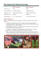
POSTMASTER SPECIFICATION Mini Postmaster Midi Postmaster Eccentric Force 50 kN 60 kN Max. post Diameter 6” (150mm) diameter 8” (200mm) diameter Hydraulic Service Double acting. 30-40 l/min Double acting. 35-46 l/min Maximum Pressure 200 BAR 200 BAR Suitable Machines 1.5 to 3 tonne Excavator 2.5 to 5 tonnes Excavator Optional Equipment A range of additional attachments are available for a variety of different posts and conditions. They are: 1.
5. Post Clamps - A wide range of clamps are available to suit posts of all shapes, sizes and material. With a drawing of the top of the post the jaws will be manufactured to suit. A range of readily available jaws are shown below.
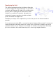
Specifying the Unit The 4 bolt mounting plate allows the fitment of brackets to suit most diggers in the quoted range. It is essential to confirm the pin diameter (D), width of boom (W), and pin pitch (C) before ordering. Not all quick hitches will be suitable for use with the Postmaster, although those designed for hammer operations should be suitable – please check with the supplier first. Standard post clamps can be adjusted for post size and specials can be devised where possible.
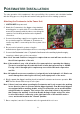
POSTMASTER INSTALLATION The safe operation of this equipment is the responsibility of the operator, who should be familiar with the lifting process, the power unit and all safety practices before starting operations. Attaching the Postmaster to the Power Unit 1. SWITCH OFF the power unit. 2. Attach the Postmaster to the digger using standard mounting pins or a quick hitch.
Pre-operation check list 1. Keep bystanders away from all moving elements. 2. Ensure you are aware of the environment you are working in; be aware of overhead cabling and other utilities services.
POST INSTALLATION Hydraulics Operation Operating the hydraulics one way causes the clamp to close, followed by the start of vibration. Reversing the flow opens the jaws without vibration. DO NOT run the machine without a post in the jaws. Jaw Selection The postmaster is supplied with a pair of universal jaws. This allows the user to install circular, semi-circular, square and rectangular posts with the same jaws but with a different configuration.
Operation Sequence The Postmaster jaws have 3 positions, accommodating posts up to 8” in diameter. First, ensure the jaws are in the correct range for the post size in use. 1. To adjust the jaws, remove the lynch pin and the static jaw pin (at the base end of the ram). Slide the jaws into the desired position, align the holes, and reinsert the jaw pin and lynch pin. 2. Stand a post vertically, and move the Postmaster into position directly above it. 3.
6. Using the boom, move the post into the desired position and push it into the surface if suitable ground. Ensure the excavator blade is lowered to add stability. 7. Start the vibration and push the post into the ground, ensuring the post is pushed vertically downwards. 8. Once the post is installed to the desired depth, simply release the jaws and lift the Postmaster away.
MAINTENANCE 1. Keep all hardware tight – re-torque regularly until stable. 2. Inspect all hoses for signs of wear and replace as necessary. 3. Inspect the rubber buffers for signs of cracking – replace promptly to prevent failure. 4. The gearbox contains 0.5 litres of universal oil. This is sufficient for 12 months operation, so annually remove the lid, pour out the old oil, check all hardware, and add 0.5 litres of new oil. DO NOT OVERFILL. Re-seal the lid using a silicone gasket sealant. 5.
SAFETY General Safety Guidance 1. The excavator should be correctly maintained and operated by a trained and competent person. 2. The banksman and machine driver need to establish a system of communication which is thoroughly understood. It may be appropriate to wear radio communication equipment in conjunction with appropriate PPE, to ensure consistent safe communication. 3. We believe that when correctly operated, the Autoguide Postmaster is safer than a conventional falling weight post driver.
SPARE PARTS LIST Postmaster 15
Code 47315 No. Code 1 2 3 4 5 6 7 8 9 10 11 49342 07420 47387 47311 47336 47343 45210 47338 47351 11752 10791 Code 48298 No.
Swing Mount Code 47341 No.
Hydraulics 18
Description MINI POSTMASTER HYDRAULICS No.
Description MIDI POSTMASTER HYDRAULICS No.
21
Description POSTMASTER HOSES - 48291 No.
Autoguide Equipment Stockley Road Heddington Nr. Calne Wiltshire SN11 0PS England Tel: +44 (0) 1380 850885 Fax: +44 (0) 1380 850010 Website: www.autoguide.co.