Code : SEA 348 ASSEMBLY MANUAL Wing Span : Approx 86.5” Length : Approx 67.3” Wing Area : Approx 1055 square inches Cowl Diameter : Approx 8-1/4” Cowl Length : Approx 8’’ deep Weight : Fully Equipped with All Rockets Drop Tanks, Bomb, Pilot Figure, Smoke tank, Smoke pump 28.5 lbs-29.
Instruction Manual. 86’’ A-1 SKYRAIDER 35-60cc WARBIRD INTRODUCTION hank you for choosing the LEGEND HOBBY 86’’ A-1 SKYRAIDER 35-60cc WARBIRD ARTF manufactured by SG MODELS. he 86’’ A-1 SKYRAIDER 35-60cc WARBIRD was designed with the intermediate/advanced sport lyer in mind. It is a semi scale airplane which is easy to ly and quick to assemble.
KIT CONTENTS INSTALL THE AILERONS SEA348 86’’ A-1 SKYRAIDER 35-60cc WARBIRD 1. Fuselage 2. Wing set (3 pcs) 3. Tail set (2 pcs) 4. Canopy 5. Cowling 6. Wing tube 7. landing gear Optional/Not Included 8. Fuel tank 9. Tail Gear Optional/Not Included 10. Pushrod set 11. Rocket Set With Deluxe Model 12. Drop Tanks/Bomb W/Deluxe Model � � � � � Please see pictures below.. 1. 2. ADDITIONAL ITEMS REQUIRED 35-60cc Engine or Electric Motor and ESC. Computer radio 6-9 channel with 8-11 servos.
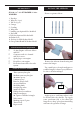
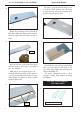
Instruction Manual. 86’’ A-1 SKYRAIDER 35-60cc WARBIRD Be sure to test the aileron hinges once you insert them. Ensure that the hinge pockets line up, and that the hinges move freely before the epoxy dries. 4. 7. Insert all four hinges in the ailerons at this time. Make sure hinges move up and down in right direction and not side to side ! 5. 8. Epoxy. Apply epoxy into each of the holes in the ailerons using a spare piece of pushrod wire or toothpick.
2. 6. INSTALLING THE AILERON SERVOS 3. 1. Epoxy. 4. Recommended Servo Spec Torque. 106.93 oz-in (7.7 kg-cm) @ 4.8V 133.31 oz-in (9.6 kg-cm) @ 6.0V Epoxy. Ailerons control horn. 5. Because the size of servos difer, you may need to adjust the size of the precut opening in the mount. he notch in the sides of the mount allow the servo lead to pass through. Place the servo between the mounting blocks and space it from the hatch. Use a pencil to mark the mounting hole locations on the blocks.
Instruction Manual. 86’’ A-1 SKYRAIDER 35-60cc WARBIRD 5. 2. Secure the servo to the aileron hatch using a proper driver and the screws provided with the servo. 6. Use drill bit in a pin vise to drill the mouting holes in the blocks. 3. 1.5mm. Apply 2-3 drops of thin C/A to each of the mounting holes. Allow the C/A to cure without using accelerator. Apply 2-3 drops of thin C/A to each of the mounting aileron hatch mounting tabs in the wing. ***Allow the C/A to cure without using accelerator.*** 7.
8. 12. 9. AILERON PUSHROD INSTALLATION Please see pictures below. 1. 65 mm. 10. 2. M3 clevis. M3 lock nut. 3. Set the aileron hatch in place and use a Phillips screw driver to install it with four wood screws. 11. 3x10mm.
Instruction Manual. 86’’ A-1 SKYRAIDER 35-60cc WARBIRD Attach the lap linkage to the control horn. Slide the clevis retainer over the forks of the clevis. INSTALLING THE FLAP PUSHROD Please see pictures below. 5. 1. 100mm. 2. M3 clevis. M3 lock nut. Attach the clevis to the lap servo arm. Attach the lap servo to the lap servo cover. Center the lap servo (or set the values to 0 for both up and down) and install the servo arm perpendicular to the servo centerline.
8. 11. Adjust the linkage so the lap is in the mid-lap position. It may take a few tries to properly adjust the linkage. Set the lap control at the transmitter to the down lap position. Adjust the lap travel at the transmitter until it matches the control throws listed in this manual. 9. 12. Once adjusted, make sure all clevis retainers are in position. Apply a drop of threadlock near the clevis, then tighten the nut against the clevis to keep the linkage from changing length inside the wing.
Instruction Manual. 86’’ A-1 SKYRAIDER 35-60cc WARBIRD 1. 14. Fit the lap linkage cover into position. Check the operation of the lap to make sure the cover does not interfere with the lap linkage. 2. 15. 3. Use canopy glue to attach the cover to the wing. Use low-tack tape to keep the cover in position until the adhesive fully cures. Blue painters tape works well ! 16. Epoxy. 4. 4x12mm WING ASSEMBLY Please study images below.
5. 1. 6. 2. Insert gear door control horn tab into hole. 7. 3. Epoxy. Apply epoxy glue to parts. INSTALLING LANDING GEAR 4. Retractable landing gear are not included. Please study images below for proper installation. You may install electric or pneumatic gear. Fuselage has accommodations for both. Allow part to completely dry. One dried completely you may proceed to next srep.
Instruction Manual. 86’’ A-1 SKYRAIDER 35-60cc WARBIRD 5. 9. Trim part to match image. Study images below. hen place a bellcrank on each end of carbon rod as shown. 6. 10. Epoxy. Put one wood ring on each end of the carbon rod. 7. Epoxy glue parts into place. 11. Epoxy. Make sure you space the wood ring so that the bellcrank and another wood ring will it on each of the carbon rods. hen epoxy into position. he inished assembly should look like this. 12. 8. Pleaae change eps to steps.
Place the actuation rod into the wing. 13. 17. Epoxy. Epoxy glue parts together. 14. 18. Epoxy. Completed Assemply. Put wooden bearing parts in the wing and CA or epoxy into place. Make sure not to glue the actuation rod. 15. 19. 16. Finished actuation rod installation.
Instruction Manual. 86’’ A-1 SKYRAIDER 35-60cc WARBIRD Install the gear door servo into the wing cover as shown below in these illustrated steps. 24. 20. 25. 21. M3x50mm. 26. 22. 27. 23. Finished gear door servo/control rod.
Install Main Retractable Landing Gear. Install aluminum pieces into the landing gear struts as shown below. 28. 32. 29. 33. 30. 3x15mm. 34. 3x6mm. 31. 35.
Instruction Manual. 86’’ A-1 SKYRAIDER 35-60cc WARBIRD Attach hinge to front gear fairing and wing. 40. 36. 41. Epoxy. 37. Epoxy. 42. 38. 43. 39. 26mm.
44. Install the cable to the cover and wing. 48. 45. 49. 46. 50. Epoxy. 47. 51.
Instruction Manual. 86’’ A-1 SKYRAIDER 35-60cc WARBIRD 52. 56. Continue Attaching the hinge to the cover and wing. 53. 57. 3x6mm. 54. 58. Epoxy. 55. 18 59.
60. 64. 61. 65. Epoxy. 66. 62. M2x30mm. 63. 67. Epoxy.
Instruction Manual. 86’’ A-1 SKYRAIDER 35-60cc WARBIRD Main Wheel installation. 68. 72. 69. 73. 70. 74. 71. 75.
76. ROCKETS INSTALLATION Please study images below. 1. 77. 2. 78. 3. Epoxy. 79. 4.
Instruction Manual. 86’’ A-1 SKYRAIDER 35-60cc WARBIRD 5. 9. Epoxy. 10. 6. Epoxy. 7. DROP TANK/BOMB INSTALLATION Please study images below. 1. 8.
2. 6. 3. 7. Epoxy. Install drop tank/bomb releases as shown. 4. 8. 2.5x10mm. 5. 9.
Instruction Manual. 86’’ A-1 SKYRAIDER 35-60cc WARBIRD 10. 14. 1.5mm. 11. 15. 2.5x10mm. Epoxy. 12. 16. 13. 17.
18. 22. 19. 23. 20. 24. 21. 25. 2.5x10mm. Epoxy.
Instruction Manual. 86’’ A-1 SKYRAIDER 35-60cc WARBIRD 26. 30. 27. If you do not wish to make the drop tanks/bomb removable you may glue them in place. Please study images below. ***We do recommend making them removable for maintenance/service of your Skyraider. 31. 28. 32. 29. 26 Epoxy.
33. 37. 34. 38. 39. 35. Epoxy. Epoxy. 36. 40.
Instruction Manual. 86’’ A-1 SKYRAIDER 35-60cc WARBIRD 41. 42. 45. 46. Epoxy. 43. 47. 44. 48.
49. 53. 50. 54. 51. 55. 52. 56.
Instruction Manual. 86’’ A-1 SKYRAIDER 35-60cc WARBIRD 57. 61. Epoxy. 2.5x10mm. 58. 62. 59. 63. 60. 64.
If you wish to make ordnance ixed you may permanently glue them in place. We recommend making them removable. 68. 65. Epoxy. 69. 66. INSTALLING THE FUSELAGE SERVOS Because the size of servos difer, you may need to adjust the size of the precut . opening in the mount. he notch in the sides of the mount allow the servo lead to pass through. 67. Secure the servos with the screws provided with your servo. 1. Elevator servo. Rudder servo + Tail wheel.
Instruction Manual. 86’’ A-1 SKYRAIDER 35-60cc WARBIRD THROTTLE SERVO ARM INSTALLATION 3. Switch. Install adjustable servo connector on the servo arm and set aside for now. 1. INSTALLING THE ENGINE SWITCH Elevator servo arm . 1. Trim and cut. Rudder servo arm. Install the rudder and elevator servo arms as shown above.
1. FUEL TANK INSTALLATION 1. 2. You should mark which tube is the vent and which is the fuel pickup when you attach fuel tubing to the tubes in the stopper. Once the tank is installed inside the fuselage, it may be diicult to determine which is which. 2. 3. Vent tube. Fuel pick up tube. Fuel ill tube. Carefully bend the second brass tube up at a 45º angle. his tube is the vent tube. Test it the stopper assembly into the tank.
Instruction Manual. 86’’ A-1 SKYRAIDER 35-60cc WARBIRD 4. Vent tube. Fuel pick up tube. 3. Fuel ill tube. Later you with connect the lines from the tank to the engine and muler. he vent line will connect to the muler and the line from the clunk to the carburetor. 4. Loctite. Blow through one of the lines to ensure the fuel lines have not become kinked inside the fuel tank compartment. Air should low through easily. MOUNTING THE ENGINE 5. Please study the images be low. 1. Loctite. 3x15mm. 6. 2.
11. 7. Locate the engine mounting in position on the irewall. Use a 2.5mm drill bit to drill the holes necessary to mount your particular engine choice. 8. 12. 2.5mm. Epoxy. 9. 13. 10. 14. 6mm.
Instruction Manual. 86’’ A-1 SKYRAIDER 35-60cc WARBIRD 15. 19. 16. 20. 17. 21. 18. 22. Inside view of the gas engine, carb, connector.
23. 27. 24. 28. Pushrod wire. Ignition Modude. 170mm. 25. 29. 26. 30.
Instruction Manual. 86’’ A-1 SKYRAIDER 35-60cc WARBIRD 35. 31. Move the throttle stick to the closed position and move the carburetor to closed. Use a 3x10mm hex wrench to tighten the screw that secures the throttle pushrod wire. Make sure to use threadlock on the screw so it does not vibrate loose. 32. 36. 33. Reinstall the servo horn by sliding the connector over the pushrod wire. Center the throttle stick and trim and install the servo horn perpendicular to the servo center line.
2. 3. 4. 5. 6. 7. 8. 9.
Instruction Manual. 86’’ A-1 SKYRAIDER 35-60cc WARBIRD 10. 14. 15. 11. 16. 12. Tape the cowl to the fuselage using low-tack tape. 13. 40 17.
18. 21. Loctite. Use a drill and drill bit to drill the holes for the cowl mounting screws. Make sure the cowl position is correct before drilling each hole. 22. 19. 23. Install the muler onto the engine and make the cutout in the cowl for muler clearance. Connect the fuel and pressure lines to the carburetor, muler and fuel iler valve. Secure the cowl to fuselage using the M3x10mm socket head screws. Putting a small length of silicone fuel tube under the head of the screw helps with vibration. 24.
Instruction Manual. 86’’ A-1 SKYRAIDER 35-60cc WARBIRD 25. INSTALL ELEVATOR HINGES Test it the hinges into the elevator, and then the hinges into the horizontal stabilzer. Ensure that the hinge pockets line up, and that the hinges move freely. Epoxy hinges the same way you did the aileron hinges. 1. INSTALLING THE PROP/HUB Install the spinner backplate, propeller and proper hub of your choice. Epoxy. 1. 2. Epoxy. he propeller should not touch any part of the cowling.
4. 4. INSTALL ELEVATOR CONTROL HORN 5. Install the elevator control horn using the same method as same as the lap control horns. 1. INSTALL RUDDER CONTROL HORN Install the rudder control horn using the same method as the aileron control horns. 2. 1. Fiberglass control horn. 3. 2. Epoxy.
Instruction Manual. 86’’ A-1 SKYRAIDER 35-60cc WARBIRD 3. 7. Epoxy. 4. 8. Epoxy. 5. 9. 6. 10. Fiberglass control horn.
INSTALLING HORIZONTAL STABLLIZER 4. 1. ELEVATOR PUSHROD HORN INSTALLATION Install the elevator control horn using the same method as with the aileron control horns. Use Epoxy to glue the Horizontal Stabilizer to the fuselage. Position the elevator control horns on both side of the elevator. 2. 1. Epoxy. 3. Elevator control horn. Epoxy. hread one clevis and M3 lock nut on to each elevator control rod. hread the horns on until they are lush with the ends of the control rods. Epoxy.
Instruction Manual. 86’’ A-1 SKYRAIDER 35-60cc WARBIRD 3. 2. Ball Link. 4. Elevator pushrod. 3. Ball Link. 5. 4. RUDDER CABLE INSTALLATION Study images below to install pull-pull cable set. 1. 46 5.
6. 7. 10. 11. 8. 12. 9. 13.
Instruction Manual. 86’’ A-1 SKYRAIDER 35-60cc WARBIRD MOUNTING THE TAIL GEAR 4. Gather tail gear components as shown below for installation. 1. 5. 2. 6. 3. 3x15mm. 7.
8. 2. 9. 3. 4. ATTACH WING TO FUSELAGE Locate the (2) 6x60mm bolts and washers. 1. 6x60mm. 6x60mm. 5.
Instruction Manual. 86’’ A-1 SKYRAIDER 35-60cc WARBIRD COCKPIT INSTALLATION 4. Locate all cockpit components as shown below. 1. 5. 2. 6. 3. 7.
8. 12. 9. 13. 10. 14. 90mm. 11. 15.
Instruction Manual. 86’’ A-1 SKYRAIDER 35-60cc WARBIRD 16. 20. 17. 21. 18. 22. Epoxy. 19. 23. Epoxy.
24. 28. Epoxy. 25. 29. Epoxy. 26. 30. Epoxy. 27. 31.
Instruction Manual. 86’’ A-1 SKYRAIDER 35-60cc WARBIRD 32. 36. 33. 37. 34. 38. 35. 39. Epoxy. 54 Epoxy.
40. 44. 41. 45. 42. 46. Epoxy. 43. 47.
Instruction Manual. 86’’ A-1 SKYRAIDER 35-60cc WARBIRD 48. 52. 49. 53. Epoxy. Epoxy. 54. 50. Epoxy. 51. 55. Epoxy.
56. 60. 57. 61. Epoxy. Epoxy. 58. 62. 59. 63. Epoxy.
Instruction Manual. 86’’ A-1 SKYRAIDER 35-60cc WARBIRD 64. 68. Epoxy. 65. 69. 66. 70. 67. 71.
72. 76. Epoxy. 77. 73. INSTALLING CANOPY 74. Trim and install as shown below. 1. 75. 2. Epoxy.
Instruction Manual. 86’’ A-1 SKYRAIDER 35-60cc WARBIRD 3. 3. Epoxy. Canopy Glue. 4. 4. AIR INTAKE INSTALLATION 5. Study images below and then install intake. 1. 6. 2.
7. 2. 8. 3. Epoxy. 9. 4. INSTALLING ANTENNAS Antennas feature banana plugs for easy installation and removal. 5. 1.
Instruction Manual. 86’’ A-1 SKYRAIDER 35-60cc WARBIRD 6. 4. INSTALL THE WING GUNS Locate the 4 Gun as seen in images below. 1. Please use scissors and/or a hobby knife to cut the decals from the sheet. Please be certain the model is cleam and free from oily ingerprints and dust. Position decal on the model where desired. You may use the photos on the box and/ or online images to aid in their location and application.
Lit the model. If the tail drops when you lit, the model is “tail heavy” and you must add weight* to the nose. If the nose drops, it is “nose heavy” and you must add weight* to the tail to balance. BALANCING - DO NOT SKIP THIS ! It is critical that your airplane be balanced correctly. Improper balance will cause your plane to lose control and crash. THE CENTER OF GRAVITY IS LOCATED 125-145MM BACK FROM THE LEADING EDGE OF THE WING AT THE WING ROOT. 1.
Instruction Manual.
FLIGHT PREPARATION PREFLIGHT CHECK Check the operation and direction of the elevator, rudder, ailerons and throttle. 1) Completely charge your transmitter and receiver batteries before your irst day of lying. A) Plug in your radio system per the manufacturer’s instructions and turn everything on. B) Check the elevator irst. Pull back on the elevator stick. he elevator halves should move up. If it they do not, lip the servo reversing switch on your transmitter to change the direction.
86’’ A-1 SKYRAIDER 35-60cc WARBIRD Instruction Manual. If you have any queries, or are interested in our products, please feel free to contact us Factory : 12/101A - Hamlet 4 - Le Van Khuong Street - Dong hanh Ward Hoc Mon District - Ho Chi Minh City - Viet Nam. Oice : 62/8 Ngo Tat To Street - Ward 19 - Binh hanh District - Ho Chi Minh City - Viet Nam Phone : 848 - 86622289 or 848- 36018777 Website : www.SeagullModels.com Email : Sales@seagullmodels.com Facebook : www.facebook.com/SeaGullModels.