MS: SEA 84 ASSEMBLY MANUAL “Graphics and specfications may change without notice”. Specifications Wingspan-------------------------------------66.9 in------------------------------- 170cm. Wing area------------------------------------764.6 sq.in-------------------- 49.3 sq.dm. Approximate flying weight----------------10.4 lbs--------------------------------4.7kg. Length----------------------------------------- 60.4in------------------------------153.3cm. Recommended engine size------------ .1.2 cu.
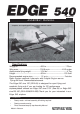
Instruction Manual EDGE 540. INTRODUCTION. Thank you for choosing the EDGE 540 ARTF by SEAGULL MODELS. The EDGE 540 was designed with the intermediate/advanced sport scale in mind. It is a semi scale airplane which is easy to fly and quick to assemble. The airframe is conventionally built using balsa, plywood to make it stronger than the average ARTF , yet the design allows the aeroplane to be kept light. You will find that most of the work has been done for you already.
www.seagullmodels.com NOTE: To avoid scratching your new aeroplane we suggest that you cover your workbench with an old towel. Keep a couple of jars or bowls handy to hold the small parts after you open the bags. Please trial fit all parts. Make sure you have the correct parts and that they fit and are aligned properly before gluing! This will ensure proper assembly as the EDGE 540 is made from natural materials and minor adjustments may have to be made.
Instruction Manual EDGE 540. 7) Repeat this process with the other wing panel, securely hinging the aileron in place. 8) After both ailerons are securely hinged, firmly grasp the wing panel and aileron to make sure the hinges are securely glued and cannot be pulled out. Do this by carefully applying medium pressure, trying to separate the aileron from the wing panel. Use caution not to crush the wing structure. AILERON CONTROL HORN Aileron control horn: See pictures below. 2 sets. 3x45mm.
www.seagullmodels.com ELEVATOR CONTROL HORN. 2 sets. Install the elevator control horn using the same method as with the aileron control horns. 2 sets. 3x45mm. CONTRONL HORN . M3 SCREW 3x45mm. ALUMINUM WASHER. CONTRONL HORN M3 EPOXY. Aluminum Washer. Epoxy. ALUMINUM WASHER. M3 LOCK NUT. Aluminum Washer. M3 LOCK NUT. EPOXY. Fuselage. Rudder. Epoxy. Horizontal Stabilizer. 16mm. 16mm. Elevator control horn. RUDDER CONTROL HORN. Rudder control horn.
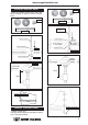
Instruction Manual EDGE 540. ENGINE MOUNT INSTALLATION. See pictures below.Make yourself the template of your engine on paper. 4x30mm. Mark and drill 4 holes for engine mount. Insert 4 blind nuts to firewall. Diameter =5.5mm. Thread locker glue. 6 INSTALLING THE STOPPER ASSEMBLY. 1) Using a modeling knife, carefully cut off the rear portion of one of the 3 nylon tubes leaving 1/2” protruding from the rear of the stopper. This will be the fuel pick up tube.
www.seagullmodels.com Vent tube. Fuel pick up tube. Fuel fill tube. Carefully use a lighter or heat gun to permenently set the angle of the vent tube. Rubber band. Fuel tank. Important: When the stopper assembly is installed in the tank, the top of the vent tube should rest just below the top surface of the tank. It should not touch the top of the tank. Vent tube. 4) Test fit the stopper assembly into the tank.
Instruction Manual EDGE 540. Landing Gear. wheel Pant. 2) Follow diagram below for wheel pant installation: 7mm. 14mm. Locker glue. Lite-Plywood block. Washer. wheel collar. 3) A drop of C/A glue on the wheel collar screws will help keep them from coming lose during operation. Axle. M3. wheel. wheel. Repeat the process for the other wheel. M3. INSTALLING THE MAIN LANDING GEAR. wheel collar. 1) The blind nuts for securing the landing gear are already mounted inside the fuselage. Washer. nut.
www.seagullmodels.com MOUNTING THE ENGINE. Machine Screw 4x30mm. 1) Install the pushrod housing through the predrilled hole in the firewall and into the servo compartment. The pushrod housing should protrude 1/4" out past the front of the firewall. Make a Z-Bend 1/4" from one end of the plain wire pushrod. 2) Place your engine onto the engine mount. Adjust the engine is centered of the edges of the engine case. 3) When you are satisfied with the alignment, mark the locations of the engine mounting.
EDGE 540. 3) Install the muffler and muffler extension onto the engine and make the cut out in the cowl for muffler clearance. Connect the fuel and pressure lines to the carburetor, muffler and fuel filler valve. Secure the cowl to fuselage using the 3x10mm screws (4). Instruction Manual 1.5mm were (needle valve). Machine Screw 3x10mm. INSTALLING THE SWITCH. SPINNER INSTALLATION. Install the switch into the precut hole in the side of fuselage.
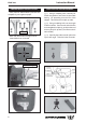
www.seagullmodels.com INSTALLING THE FUSELAGE SERVO. Because the size of servos differ, you may need to adjust the size of the precut opening in the mount. The notch in the sides of the mount allow the servo lead to pass through. 1) Install the rubber grommets and brass collets onto the throttle servo. Test fit the servo into the aileron servo mount. VERTICAL STABILIZER INSTALLATION. Remove the covering as picture shown below. Remove covering.
Instruction Manual EDGE 540. Covering strip. Hinge. Epoxy. C/A glue. INSTALLING HORIZONTAL FIN. 1) Remove the covering as same as pictures shown below. 2) Sand the aluminium tube using sandpaper. This will improve the bond of the epoxy to the cardboard horizontal fin. Coat both sides of one half of the aluminium tube with 30 minute epoxy. Next, pour some epoxy into the cardboard horizontal fin. Use enough epoxy to fill any gaps. Hinge slot. 335mm. Aluminium tube. Epoxy.
www.seagullmodels.com INSTALLING THE AILERON SERVOS. Servos. Small weight. Thread. String. Small weight. Installing the aileron servo in place using the same techniques used to flap servo. Aileron Servo. Wing. String. Electric wire. Epoxy. Epoxy. Wing rib. Small Weight. Small Weight. String. Attach the string to the servo lead and carefully thread it though the wing.
Instruction Manual EDGE 540. Wing. AILERON PUSHROD HORN INSTALLATION 75mm. M2 clevis. Aileron. M2 lock nut. 110mm. Wing. Wing. Aileron. Aileron. ELEVATOR - RUDDER PUSHROD HORN INSTALLATION. M2 lock nut. Rudder control horn. Elevator control horn. Wing. Aileron. Repeat the procedure for the other wing. 1) Elevator and rudder pushrods assembly follow pictures below. M2 clevis. Attach to servo arm in fuselage. 14 M2 Lock nut. Attach to elevator - rudder control horn.
www.seagullmodels.com Throttle. Elevator. Rudder. Elevator. Elevator Pushrod. Control horn. Throttle. Rudder. M2 lock nut. Metal clevis. Elevator. MOUNTING THE TAIL WHEEL. See picture below. Elevator pushrod. Rudder pushrod. 2) Install servos arm to servos. Notice the position of the servo arms on the servos. See picture below. 3x25mm. 3x30mm.
Instruction Manual EDGE 540. 3x25 mm. Receiver. 3x30 mm. 3x30 mm. Antenna. ATTACHMENT WING-FUSELAGE. Attach the aluminium tube into fuselage. Wing tube. Spring. Tail landing gear. INSTALLING THE BATTERY-RECEIVER. 1) Plug the six servo leads and the switch lead into the receiver. Plug the battery pack lead into the switch also. 2) Wrap the receiver and battery pack in the protective foam rubber to protect them from vibration.
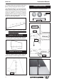
www.seagullmodels.com Wing bolt. 6.5-7.5cm. 4x15mm. CONTROL THROWS. BALANCING. 1) It is critical that your airplane be balanced correctly. Improper balance will cause your plane to lose control and crash. The center of gravity is locate 6.5-7.5cm back from the leading edge of the wing, measured at wing tip. 2) If the nose of the plane falls, the plane is nose heavy. To correct this first move the battery pack further back in the fuselage.
Instruction Manual EDGE 540. INITIAL FLYING AEROBATIC FLYING Do not use the aerobatic settings for initial test flying or sport flying. 4) By moving the position of the adjustable control horn out from the control surface, you will decrease the amount of throw of that control surface. Moving the adjustable control horn toward the control surface will increase the amount of throw. FLIGHT PREPARATION. A) Check the operation and direction of the elevator, rudder, ailerons and throttle.
www.seagullmodels.com 2) Check every bolt and every glue joint in the EDGE 540 to ensure that everything is tight and well bonded. 6) Check to ensure the control surfaces are moving the proper amount for both low and high rate settings. 3) Double check the balance of the airplane. Do this with the fuel tank empty. 7) Check the receiver antenna. It should be fully extended and not coiled up inside the fuselage. 4) Check the control surfaces.