(Glider) MS:137 ASSEMBLY MANUAL “Graphics and specifications may change without notice”. Specifications: Wing span -------------------------------------------- 118.1in (300cm). Wing area ---------------------------------------- 899sq.in (58sq dm). Weight ---------------------------------------------------- 6.2lbs (2.8kg). Length -------------------------------------------------- 57.1in (145cm). Radio --------------------------------------------------------- 6 channels.
Instruction Manual. KA8-B INTRODUCTION. Thank you for choosing the KA8-B ARTF by SEAGULL MODELS. The KA8-B was designed with the sports trainer flyer in mind. It is a High-wing aeroplane which is easy to fly and quick to assemble. The airframe is conventionally built using balsa, plywood and veneer to make it stronger than the average ARTF , yet the design allows the aeroplane to be kept light. You will find that most of the work has been done for you already.
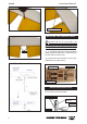
Instruction Manual. HINGING THE RUDDER . Note: The control surfaces, including the ailerons, elevators, and rudder, are prehinged with hinges installed, but the hinges are not glued in place. It is imperative that you properly adhere the hinges in place per the steps that follow using a high-quality thin C/A glue. Hinge. 1) Carefully remove the aileron from one of the wing panels. Note the position of the hinges. 4)Deflect the aileron and completely saturate each hinge with thin C/A glue.
KA8-B Instruction Manual. HINGING THE ELEVATOR . 5) Turn the wing panel over and deflect the aileron in the opposite direction from the opposite side. Apply thin C/A glue to each hinge, making sure that the C/A penetrates into both the aileron and wing panel. 6) Using C/A remover/debonder and a paper towel, remove any excess C/A glue that may have accumulated on the wing or in the aileron hinge area. 7) Repeat this process with the other wing panel, securely hinging the aileron in place.
Instruction Manual. INSTALL THE AILERON CONTROL HORN . 1) Locate the hardware necessary to install the control horns for the ailerons. 3x35mm. 2 sets. 2) Position the control horn on the bottom of the aileron. You will see pre-drill hole 6mm for the horn mounting screw on the aileron. Aileron control horn. 6mm. ELEVATOR CONTROL HORN INSTALLATION. 3) Place epoxy into hole. This will harden the threads and prevent the crews from pulling loose.
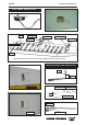
Instruction Manual. KA8-B Elevator control horn. INSTALLING THE FUSELAGE SERVO. Because the size of servos differ, you may need to adjust the size of the precut opening in the mount. The notch in the sides of the mount allow the servo lead to pass through. 6mm. 1) Install the rubber grommets and brass collets onto the throttle servo. Test fit the servo into the aileron servo mount. 2) Secure the servos with the screws provided with your radio system. Rudder servo . Throttle servo . Elevator servo .
Instruction Manual. AILERON SERVO INSTALLATION. Rudder servo arm. Servos. Throttle servo arm. Elevator servo arm. INSTALLING THE SWITCH. Install the switch into the precut hole in the side of fuselage. Because the size of servos differ, you may need to adjust the size of the precut opening in the mount. The notch in the sides of the mount allow the servo lead to pass through. 2) Using a small weight (Weighted fuel pick-up works well) and string, feed the string through the wing as indicated.
Instruction Manual. KA8-B FLAP SERVO INSTALLATION. Wing. Flap servo. Aileron servo. Wing rib. M2x6mm. M2x6mm. Small weight. String. Attach the string to the servo lead and carefully thread it though the wing. AILERON PUSHROD HORN INSTALLATION Cut. 8mm Aileron servo. M2 lock nut. Metal clevis. 8mm Snap keeper. Servo arm. Flap servo. 8 Snap keeper.
Instruction Manual. C/A glue. Repeat the procedure aileron servo. for the other AIRBREAKES PUSHROD CONTROL HORN INSTALLATION. M2x6mm. C/A glue.
Instruction Manual. KA8-B ELEVATOR PUSHROD INSTALLATION. 678mm. Cut. THE HORIZONTAL STABILIZER INSTALLATION. M3x30mm. M3x30mm.
Instruction Manual. 3mm Cut. 8m m Pen. 8mm Snap keeper.
Instruction Manual. KA8-B RUDDER PUSHROD. M2 lock nut. Metal clevis. 8mm Snap keeper. Servo arm. Snap keeper. M2x12mm. Pen. 8mm Cut.
Instruction Manual. Cut. SERVO INSTALLATION. The tow hook. C/A glue. The above is the tow hook position. C/A glue. Cut.
Instruction Manual. KA8-B INSTALLING THE RECEIVER AND BATTERY. 1) Plug the five servo leads and the switch lead into the receiver. Plug the battery pack lead into the switch also. 2) Wrap the receiver and battery pack in the protective foam rubber to protect them from vibration. Wing bolt. 3) Route the antenna in the antenna tube inside the fuselage and secure it to the bottom of fuselage using a plastic tape. Receiver. Battery. ATTACHMENT WING -FUSELAGE. BALANCING.
Instruction Manual. Accurately mark the balance point on the top of the wing on both sides of the fuselage. The balance point is located 60 mm back from the leading edge of the wing at the wing root. This is the balance point at which your model should balance for your first flights. Later, you may wish to experiment by shifting the balance up to 10mm forward or back to change the flying characteristics.
Instruction Manual. KA8-B FLIGHT PREPARATION. PREFLIGHT CHECK. A) Check the operation and direction of the elevator, rudder, ailerons and throttle. 1) Completely charge your transmitter and receiver batteries before your first day of flying. B) Plug in your radio system per the manufacture’s instructions and turn every thing on. C) Check the elevator first. Pull back on the elevator stick. The elevator halves should move up.