DECATHLON Hand-made Almost Ready to Fly R/C Model Aircraft ASSEMBLY MANUAL SPECIFICATIONS: WING SPAN ----------------------------------------172CM -------------------------------- 67.75 in. WING AREA --------------------------------------49.17Sq.dm -----------------------------762Sq.in. WEIGHT ---------------------------------------3.17 - 3.62KG ----------------------- 7- 8lbs. ENGINE SIZE ------------------------ .40 - .46 cu. in----------------------------------- 2-stroke. ------------ .50 - .72 cu.
Instruction Manual DECATHLON INTRODUCTION Thank you for choosing the DECATHLON ARTF by SEAGULL MODELS. The DECATHLON was designed with the intermediate/advanced sport flyer in mind. It is a semi scale airplane which is easy to fly and quick to assemble. The airframe is conventionally built using balsa, plywood and veneer to make it stronger than the average ARTF , yet the design allows the aeroplane to be kept light. You will find that most of the work has been done for you already.
DECATHLON INSTRUCTION MANUAL NOTE: To avoid scratching your new aeroplane we suggest that you cover your workbench with an old towel. Keep a couple of jars or bowls handy to hold the small parts after you open the bags. Please trial fit all parts. Make sure you have the correct parts and that they fit and are aligned properly before gluing! This will ensure proper assembly as the DECATHLON is made from natural materials and minor adjustments may have to be made.
DECATHLON HINGING THE AILERONS Note: The control surfaces, including the ailerons, elevators, and rudder, are prehinged with hinges installed, but the hinges are not glued in place. It is imperative that you properly adhere the hinges in place per the steps that follow using a high-quality thin CA glue. ✑ 1) Carefully remove the aileron from one of the wing panels. Note the position of the hinges. Instruction Manual ✑ 4)Deflect the aileron and completely saturate each hinge with thin CA glue.
DECATHLON INSTRUCTION MANUAL ✑ 7) Repeat this process with the other wing panel, securely hinging the aileron in place. ✑ 8) After both ailerons are securely hinged, firmly grasp the wing panel and aileron to make sure the hinges are securely glued and cannot be pulled out. Do this by carefully applying medium pressure, trying to separate the aileron from the wing panel. Use caution not to crush the wing structure.
Instruction Manual DECATHLON ✑ 6) Using CA remover/debonder and a paper towel, remove any excess CA glue that may have accumulated on the horizontal stabilizer or in the elevator hinge area. ✑ 7) Repeat this process with the other horizontal stabilizer panel, securely hinging the elevator in place. ✑ 8) After both horizontal stabilizer are securely hinged, firmly grasp the horizontal stabilizer panel and elevator to make sure the hinges are securely glued and cannot be pulled out.
INSTRUCTION MANUAL DECATHLON Note: Work the rudder up and down several times to “work in” the hinges and check for proper movement. WING ASSEMBLY. NOTE: We highly recommend using 30 minute epoxy as it is stronger and provides more working time, allowing the builder to properly align the parts. Using fast cure epoxy when joining the wing halves could result in the glue drying before the wing halves are aligned properly which may result in failure of the wing centre section during flight.
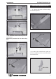
Instruction Manual DECATHLON ✑ 2) Install the rubber grommets and brass collets onto the aileron servo. Test fit the servo into the aileron servo mount. Because the size of servos differ, you may need to adjust the size of the precut opening in the mount. The notch in the sides of the mount allow the servo lead to pass through. Small weight. Masking tape. Thread. Use a small weight (Weighted fuel pick-up) and thread to feed the servo connector through the wing as shown. INSTALLING THE AILERON SERVOS.
INSTRUCTION MANUAL DECATHLON Thread. INSTALLING THE AILERON LINKAGE ✑ 1) Using a ruler & pen to draw a straight line as below picture. Servo electric wire. Servo arm. ✑ 3) Install the aileron servo tray into the servo mount. Repeat the procedure for the other wing half. Plastic tape. Line. ✑ 2) Locate nylon control horns, nylon control horn backplates and 2 control horns bolts come with 2 nuts. Servo arm. 2MM x 20MM.
Instruction Manual DECATHLON ✑ 3) Position the aileron horn on the bottom side of aileron. The clevis attachment holes should be positioned over the hinge line as shown below. Control Horn. ✑ 6) Thread one clevis control horn onto each aileron torque rod. Thread the clevis on until they are flush with the ends of the torque rods. Clevis. Aileron Torque rod. Mounting Screws. Mounting Plate. ✑ 4) Using a 1.
INSTRUCTION MANUAL DECATHLON FUEL TANK ✑ ✑ ✑ ✑ {1} {1} {1} {1} PARTS REQUIRED Molded Nylon Fuel Tank Preassembled Stopper Assembly Metal Weighted Pick-Up Silicon tube INSTALLING THE STOPPER ASSEMBLY ✑ 1) Using a modeling knife, carefully cut off the rear portion of one of the 3 nylon tubes leaving 1/2” protruding from the rear of the stopper. This will be the fuel pick up tube.
Instruction Manual DECATHLON Vent tube. Fuel fill Tube. Fuel Pickup Tube. 4MMx30MM. Engine mount. Blow through one of the lines to ensure the fuel lines have not become kinked inside the fuel tank compartment. Air should flow through easily. MOUNTING THE ENGINE ✑ 1)Trial fit your engine on the motor mount. The engine should be positioned so there is ample clearance in the cowling for spinner backplate mounted to the prop drive shaft. ✑ 2)Marking 4 points on the plastic motor mount.
INSTRUCTION MANUAL DECATHLON ✑ 1) Assemble and mounting the wheel pants as shown in the following pictures. ✑ 2) Follow diagram below for wheel pant installation: (2) Washer. (2) Washer. (2) Wheel Collar. Axle. Nut. Wheel Collar. Wheel. Axle. Nut. Nut. Nut. Wheel. Landing Gear. Wheel Pant. 10 mm. Landing gear. ✑ 3) You have to trim each axle using a toll cutting and cut-off wheel. Caution when cutting the axles and wear protective goggles.
Instruction Manual DECATHLON 3mm X 12mm. INSTALLING THE MAIN LANDING GEAR ✑ 1) The blind nuts are already mounted inside the fuselage. ✑ 2) The holes in the landing gear should be to accept the mounting bolts. ✑ 3) Using the hardware provided, mount the main landing gear to the fuselage. ✑ 2) While keeping the back edge of the cowl flush with the marks, align the front of the cowl with the crankshaft of the engine.
DECATHLON INSTRUCTION MANUAL ✑ 3) Slide the cowl back over the engine and secure it in place using four wood screws.See picture below. ✑ 4) Install the muffler and muffler extension onto the engine and make the cutout in the cowl for muffler clearance. Connect the fuel and pressure lines to the carburetor, muffler and fuel filler valve. Exhaut hole needed to drill 20 - 30 mm diameter. ✑ 5) It is recommended to install a Muffler extension. ( this item is not include ).
Instruction Manual DECATHLON Pen. ✑ 3) With the stabilizer held firmly in place, use a pen and draw lines onto the stabilizer where it and the fuselage sides meet. Do this on both the right and left sides and top and bottom of the stabilizer. ✑ 4) Remove the stabilizer. Using the lines you just drew as a guide, carefully remove the covering from between them using a modeling knife. ✑ 7) After the epoxy has fully cured, remove the masking tape or T-pins used to hold the stabilizer in place.
INSTRUCTION MANUAL DECATHLON ✑ 2) Slide the vertical stabilizer into the slot in the top of the fuselage. The rear edge of the stabilizer should be flush with the rear edge of the fuselage and the lower rudder hinge should engage the precut hinge slot in the lower fuselage. The bottom edge of the stabilizer should also be firmly pushed against the top of the horizontal stabilizer. Pen.
Instruction Manual DECATHLON CONTROL HORN INSTALLTION ✑ 1) Locate the two nylon control horns, two Elevator control horn. nylon control horn backplates and four machine screws. ✑ 2) Position the elevator horn on the both side of elevator. The clevis attachment holes should be positioned over the hinge line. 2MM x 20MM. Rudder control horn. Control Horn. ELEVATOR - RUDDER PUSHROD INSTALLATION Mounting Screws. Mounting Plate. Elevator pushrod. ✑ 3) Using a 1.
INSTRUCTION MANUAL DECATHLON MOUNTING THE CONTROL CLASP 1. Align the tail wheel wire so that the wire is parallel with the bottom of the rudder. The control clasp has a predrilled hole through the top of it. Slide this hole onto the tail wheel wire while sliding the clasp over the bottom of the rudder. 2. Using a ruler and a pen place a mark onto the bottom of the rudder. The back edge of the clasp should line up with this mark.
Instruction Manual DECATHLON INSTALLING THE RECEIVER AND BATTERY Rudder. Elevator. Elevator. ✑ 1) Plug the five servo leads and the switch lead into the receiver. Plug the battery pack lead into the switch also. Throttle. ✑ 2) Wrap the receiver and battery pack in the protective foam rubber to protect them from vibration. ✑ 6) Install adjustable servo connector in the servo arm. Adjustable Servo connector.
INSTRUCTION MANUAL DECATHLON Installing alumium plate follow picture below: Alumium plate. Alumium plate. WING STRUT INSTALLATION Parts requirement. See picture below: 4 pcs. 2 pcs.
Instruction Manual DECATHLON ✑ 2) Turn on the radio system, and with the trim tabs on the transmitter in neutral, center the control surfaces by making adjustments to the clevises or adjustable servo connectors. The servo arms should be centered also. ✑ 3) When the elevator, rudder and aileron control surfaces are centered, use a ruler and check the amount of the control throw in each surface.
DECATHLON ✑ E) Check the throttle. Moving the throttle stick forward should open the carburetor barrel. If it does not, flip the servo reversing switch on your transmitter to change the direction. ✑ F) From behind the airplane, look at the aileron on the right wing half. Move the aileron stick to the right. The right aileron should move up and the other aileron should move down. If it does not, flip the servo reversing switch on your transmitter to change the direction.