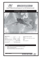
Hand-made Almost Ready to Fly R/C Model Aircraft ASSEMBLY MANUAL “Graphics and Specfications may change without notice”. Specifications Length---------------------------------122.3cm--------------- 48in. Wingspan-----------------------------160cm----------------- 63in. Wing area-----------------------------4047sp cm ---- 627sp in. Approximate flying weight--------2.8-2.95kg. --- 6.2-6.5lbs. Recommended engine size-----------------.40-.48 2-stroke. ----------------.50-.72 4-stroke.
SPACE WALKER II Instruction Manual. INTRODUCTION. Thank you for choosing the SPACE WALKER II ARTF by SEAGULL MODELS. The SPACE WALKER II was designed with the intermediate/advanced sport flyer in mind. It is a semi scale airplane which is easy to fly and quick to assemble. The airframe is conventionally built using balsa, plywood and veneer to make it stronger than the average ARTF , yet the design allows the aeroplane to be kept light. You will find that most of the work has been done for you already.
SPACE WALKER II NOTE: To avoid scratching your new aeroplane we suggest that you cover your workbench with an old towel. Keep a couple of jars or bowls handy to hold the small parts after you open the bags. Please trial fit all parts. Make sure you have the correct parts and that they fit and are aligned properly before gluing! This will ensure proper assembly as the Space Walker II is made from natural materials and minor adjustments may have to be made.
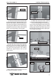
SPACE WALKER II 5) Turn the wing panel over and deflect the aileron in the opposite direction from the opposite side. Apply thin C/A glue to each hinge, making sure that the C/A penetrates into both the aileron and wing panel. 6) Using C/A remover/debonder and a paper towel, remove any excess C/A glue that may have accumulated on the wing or in the aileron hinge area. 7) Repeat this process with the other wing panel, securely hinging the aileron in place. Instruction Manual. Apply epoxy glue.
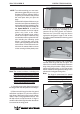
INSTRUCTION MANUAL. SPACE WALKER II Wing tube. Masking tape. 2) Remove the brace when satisfied with its fit ineach wing half. Coat both sides of one half of the dihedral brace with 30 minute epoxy. Next, pour some epoxy into the dihedral box in one wing panel. Make sure you cover the top and bottom as well as the sides of the dihedral brace. Use enough epoxy to fill any gaps. 3) When the epoxy has cured, carefully remove the masking tape from the wing.
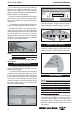
Instruction Manual. SPACE WALKER II 1) Install the rubber grommets and brass collets onto the aileron servo. Test fit the servo into the aileron servo mount. Because the size of servos differ, you may need to adjust the size of the precut opening in the mount. The notch in the sides of the mount allow the servo lead to pass through. Electric wire. Secure the servos with the screws provided from your radio system.
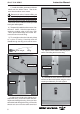
INSTRUCTION MANUAL. SPACE WALKER II Repeat the procedure for the other wing half. AILERON LINKAGE. 1) Using a ruler & pen to draw a straight line as below picture. 4) Using a 1mm drill bit and the control horns as a guide, drill the mounting holes through the aileron halves. 5) Mount the control horns by inserting the screws through the control horn bases and aileron halves, then into the mounting backplates. Do not overtighten the screws or the backplates may crush the wood. Pen.
Instruction Manual. SPACE WALKER II Important: When the stopper assembly is installed in the tank, the top of the vent tube should rest just below the top surface of the tank. It should not touch the top of the tank. Wire keeper. Servo arm. 9) Connect the linkage as shown and secure the control wire with a wire keeper. 4) Test fit the stopper assembly into the tank. It may be necessary to remove some of the flashing around the tank opening using a modeling knife.
INSTRUCTION MANUAL. SPACE WALKER II You should mark which tube is the vent and which is the fuel pickup when you attach fuel tubing to the tubes in the stopper. Once the tank is installed inside the fuselage, it may be difficult to determine which is which. Slide the tank into the fuselage from inside so that the neck is at the top of the fuselage and it locates through the engine bulkhead. Gently secure it to the top horizontal former with a cable tie. 11cm. 2) Place your engine onto the engine mount.
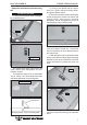
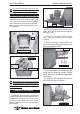
Instruction Manual. SPACE WALKER II COWLING. 1) Slide the fiberglass cowl over the engine and line up the back edge of the cowl with the marks you made on the fuselage. 2) While keeping the back edge of the cowl flush with the marks, align the front of the cowl with the crankshaft of the engine. The front of the cowl should be positioned so the crankshaft is in the middle of the cowl opening. Hold the cowl firmly in place using pieces of masking tape.
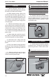
INSTRUCTION MANUAL. SPACE WALKER II 5mm. 10mm. 3) You have to trim each axle using a tool cutting and cut-off wheel. WHEEL AND WHEEL PANTS. 1) Assemble and mounting the wheel pants as shown in the following pictures. Caution when cutting the axles and wear protective goggles. 46mm. 2) Follow diagram below for wheel pant installation: (2) Washer. Wheel Collar. Axle. Nut. (2) Washer. Wheel. Nut. (2) Wheel Collar. Landing Gear. Wheel Pant. Axle. Wheel. Nut. Nut.
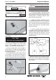
Instruction Manual. SPACE WALKER II Landing gear. 4mm X 20mm. HORIZONTAL STABILIZER. 1) Using a ruler and a pen, locate the centerline of the horizontal stabilizer, at the trailing edge, and place a mark. Use a triangle and extend this mark, from back to front, across the top of the stabilizer. Also extend this mark down the back of the trailing edge of the stabilizer. Draw center line. 2) Slide the stabilizer into place in the precut slot in the rear of the fuselage.
INSTRUCTION MANUAL. SPACE WALKER II Pen. 4) Remove the stabilizer. Using the lines you just drew as a guide, carefully remove the covering from between them using a modeling knife. Remove covering. 7) After the epoxy has fully cured, remove the masking tape or T-pins used to hold the stabilizer in place. Carefully inspect the glue joints. Use more epoxy to fill in any gaps that may exist that were not filled previously and clean up the excess using a paper towel and rubbing alcohol.
Instruction Manual. SPACE WALKER II 2) Slide the vertical stabilizer into the slot in the top of the fuselage. The rear edge of the stabilizer should be flush with the rear edge of the fuselage and the lower rudder hinge should engage the precut hinge slot in the lower fuselage. The bottom edge of the stabilizer should also be firmly pushed against the top of the horizontal stabilizer. Remove covering.
INSTRUCTION MANUAL. SPACE WALKER II Rudder control horn. CONTROL HORN INSTALLTION. PUSHROD INSTALLATION. 1)Elevator and rudder control horn in place using the same techinques to aleron control horn.See picture below. 2) Position the elevator horns on the one side of elevator. The clevis attach- ment holes should be positioned over the hinge line. Elevator pushrod. 2mm X 20mm. Rudder pushrod. Control Horn. Mounting Screws. Mounting Plate.
Instruction Manual. SPACE WALKER II 3) While holding the clasp firmly in place, use a pen and outline the clasp onto the rudder. 4) Remove the clasp, and using a modeling knife, remove the covering from inside the lines you drew. Use 220 grit sandpaper and carefully roughen the inside surface of the nylon clasp. 5) Slide the clasp back into position and carefully glue it into place using Kwik Bond Thin C/A. Hold the clasp in place until the glue completely cures. Secure by 1 machine screw. Control clasp.
INSTRUCTION MANUAL. SPACE WALKER II Servo arm. Adjustable Servo connector. LANDING GEAR C/A glue. ( 3 PCS). Thread locker glue. 6) Connect the elevator, rudder and throttle servos to your radio’s receiver and turn on the system. Set the trim tabs on the transmitter to neutral and center the servo arms. The elevator, rudder and throttle servo arms should be perpendicular to the servos. 7) One at a time, hold the pushrods in position over the respective servos to check for proper servo direction.
Instruction Manual. SPACE WALKER II When balanced correctly, the airplane should sit level or slightly nose down when you lift it up with your fingers. Silicon glue. 2M x 8mm. 10mm. 10mm. 7,5-8cm. CONTROL THROWS. ATTACHMENT WING - FUSELAGE. Bolt the wing to fuselage. Wing bolt. BALANCING. 1) It is critical that your airplane be balanced correctly. Improper balance will cause your plane to lose control and crash.
SPACE WALKER II 4) By moving the position of the adjustable control horn out from the control surface, you will decrease the amount of throw of that control surface. Moving the adjustable control horn toward the control surface will increase the amount of throw. FLIGHT PREPARATION. 1) Check the operation and direction of the elevator, rudder, ailerons and throttle. A) Plug in your radio system per the manufacturer's instructions and turn everything on. B) Check the elevator first.
SPACE WALKER II Instruction Manual. FOR USA MARKET ONLYLY. Warranty Period: Exclusive Warranty- Horizon Hobby, Inc., (Horizon) warranties that the Products purchased (the “Product”) will be free from defects in materials and workmanship at the date of purchase by the Purchaser. Limited Warranty (a) This warranty is limited to the original Purchaser (“Purchaser”) and is not transferable. REPAIR OR REPLACEMENT AS PROVIDED UNDER THIS WARRANTY IS THE EXCLUSIVE REMEDY OF THE PURCHASER.
INSTRUCTION MANUAL. SPACE WALKER II Warranty Inspection and Repairs To receive warranty service, you must include your original sales receipt verifying the proof-of-purchase date. Provided warranty conditions have been met, your Product will be repaired or replaced free of charge. Repair or replacement decisions are at the sole discretion of Horizon Hobby.
SPACE WALKER II 22 Instruction Manual.