PERCIVAL MEW GULL MS: SEA 98 ASSEMBLY MANUAL “Graphics and specfications may change without notice”. Specifications Wingspan-------------------------------------74 in---------------------------------- 188cm. Wing area------------------------------------797.2 sq.in-------------------- 51.4 sq.dm. Approximate flying weight----------------10.1-11lbs------------------------4.6 - 5kg. Length------------------------------------------60.7in------------------------------154.3cm.
Instruction Manual PERCIVAL MEW GULL INTRODUCTION. Thank you for choosing the PERCIVAL MEW GULL ARTF by SEAGULL MODELS. The PERCIVAL MEW GULL was designed with the intermediate/advanced sport scale in mind. It is a semi scale airplane which is easy to fly and quick to assemble. The airframe is conventionally built using balsa, plywood to make it stronger than the average ARTF , yet the design allows the aeroplane to be kept light. You will find that most of the work has been done for you already.
www.seagullmodels.com NOTE: To avoid scratching your new aeroplane we suggest that you cover your workbench with an old towel. Keep a couple of jars or bowls handy to hold the small parts after you open the bags. Please trial fit all parts. Make sure you have the correct parts and that they fit and are aligned properly before gluing! This will ensure proper assembly as the PERCIVAL MEW GULL is made from natural materials and minor adjustments may have to be made.
Instruction Manual PERCIVAL MEW GULL 7) Repeat this process with the other wing panel, securely hinging the aileron in place. AILERON CONTROL HORN 8) After both ailerons are securely hinged, firmly grasp the wing panel and aileron to make sure the hinges are securely glued and cannot be pulled out. Do this by carefully applying medium pressure, trying to separate the aileron from the wing panel. Use caution not to crush the wing structure. Aileron control horn installation: See pictures below. 2 sets.
www.seagullmodels.com ELEVATOR CONTROL HORN. Install the elevator control horn using the same method as with the aileron control horns. RUDDER CONTROL HORN. Rudder control horn: Using the same techniques used aileron control horn. See picture below. 2 sets. 3x45mm. 2 sets. 3x50mm. CONTRONL HORN CONTRONL HORN M3 . M3 SCREW ALUMINUM WASHER. Aluminum Washer. EPOXY. Epoxy. Horizontal Stabilizer. Elevator. FUSELAGE ALUMINUM WASHER. Aluminum Washer. M3 LOCK NUT. M3 LOCK NUT. EPOXY.
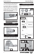
PERCIVAL MEW GULL ENGINE MOUNT INSTALLATION. Instruction Manual 3) Carefully bend the second nylon tube up at a 45º angle. This tube is the vent tube. See pictures below.Make yourself the template of your engine on paper. M4 x 30mm. Mark and drill 4 holes for engine mount. Insert 4 blind nuts to firewall. Thread locker glue Vent tube Fuel pick up tube INSTALLING THE STOPPER ASSEMBLY.
www.seagullmodels.com 4) Test fit the stopper assembly into the tank. It may be necessary to remove some of the flashing around the tank opening using a modeling knife. If flashing is present, make sure none falls into the tank. 5) With the stopper assembly in place, the weighted pick-up should rest away from the rear of the tank and move freely inside the tank. The top of the vent tube should rest just below the top of the tank. It should not touch the top of the tank.
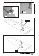
Instruction Manual PERCIVAL MEW GULL 2) Insert the 90o bend of one main gear wire and support mounting block into the predrilled hole in one mounting slot Remove covering. A B Pen. M3 x 25mm. Epoxy.
www.seagullmodels.com Trim and cut. B A M3 x 10mm.
PERCIVAL MEW GULL Instruction Manual Wheel. Axle. Wheel collar. M3x10mm.
www.seagullmodels.com M3 x 10mm. 150mm. 4.2 mm diameter MOUNTING THE ENGINE. 1) Install the pushrod housing through the predrilled hole in the firewall and into the servo compartment. The pushrod housing should protrude 1/4" out past the front of the firewall. Make a Z-Bend 1/4" from one end of the plain wire pushrod. 2) Place your engine onto the engine mount. Adjust the engine is centered of the edges of the engine case.
Instruction Manual PERCIVAL MEW GULL Machine Screw M3x10mm. COWLING INSTALLATION. Trim and cut. Trim and cut. 2. Electric Conversion (Ep Power) (OPTION). 4.2 mm Trim and cut.
www.seagullmodels.com 4 sets. Aluminum tube. B Aluminum spacers. A Aluminum spacers. M6 x 120mm. Aluminum tube. B B B B Aluminum tube. M5 nut. Electric motor. M3 x 15mm. M6x 120mm. 1 2 Battery hatch. A Electric motor.
Instruction Manual PERCIVAL MEW GULL 1 C/A glue. Battery hatch. 2 Battery SPINNER INSTALLATION. Battery hatch Needle vavle. 2 Pen Trim and cut. Trim and cut.
www.seagullmodels.com INSTALLING THE FUSELAGE SERVO. Throttle servo arm. Elevator servo. Elevator servo . Throttle servo . Rudder servo Rudder servo . Elevator servo. Elevator servo . INSTALLING THE AILERON SERVOS. INSTALLING THE SWITCH. Install the switch into the precut hole in the side of fuselage. Servos. Small weight. Thread. Installing the aileron servo in place using the same techniques used to flap servo. Switch. Small weight. String. Aileron Servo. Electric wire.
Instruction Manual PERCIVAL MEW GULL INSTALLING THE AILERON SERVOS Wing rib. Small weight. Small weight. String. Attach the string to the servo lead and carefully thread it though the wing. AILERON PUSHROD HORN INSTALLATION 85mm. M3 clevis. M3 lock nut. 110mm. Wing. Wing. Aileron. Aileron.
www.seagullmodels.com Wing. M3 lock nut. Aileron. Masking tape. Repeat the procedure for the other wing. WING ASSEMBLY. MOUNTING THE TAIL WHEEL See pictures below. Aluminum tube diameter = 19 x 577 mm. Masking tape. M3 x 25mm. Epoxy. M3 x 25mm.
Instruction Manual PERCIVAL MEW GULL INSTALLING VERITICAL FIN. 1) Remove the covering as picture shown below. Epoxy. Hinge. Hinge slot. Masking tape. Cut. Remove the covering. Epoxy. Epoxy. Epoxy. Cut. Covering strip. Hinge. Epoxy. 18 C/A glue.
www.seagullmodels.com INSTALLING HORIZONTAL FIN. Epoxy. Aluminium tube diameter=12x208mm. 3 x 70mm. Epoxy. Cut Fill epoxy. Epoxy. Epoxy.
Instruction Manual PERCIVAL MEW GULL Rudder control horn. Elevator control horn. ELEVATOR - RUDDER PUSHROD HORN INSTALLATION. 1) Elevator and rudder pushrods assembly follow pictures below. M2 clevis. M2 lock nut. Attach to servo arm in fuselage Attach to elevator - rudder control horn. Throttle. Rudder. Control horn. Metal clevis. M2 lock nut. Elevator. Elevator pushrod. Elevator Pushrod. Rudder pushrod.
www.seagullmodels.com Elevator. C/A glue. Throttle. Rudder. A. Elevator. INSTALLING THE RECEIVER. A. Receiver. Tie Wrap. A. Epoxy. Antenna.
Instruction Manual PERCIVAL MEW GULL ATTACHMENT WING - FUSELAGE. CONTROL THROWS. 1) We highly recommend setting up the PERCIVAL MEWGULL using the control throws listed at right. We have listed control throws for both Low Rate (initial test flying/sport flying) (aerobatic flying). Wing bolt. 2) Turn on the radio system, and with the trim tabs on the transmitter in neutral, center the control surfaces by making adjustments to the clevises or adjustable servo connectors.
www.seagullmodels.com D) Check the rudder. Looking from behind the airplane, move the rudder stick to the right. The rudder should move to the right. If it does not, flip the servo reversing switch on your transmitter to change the direction. E) Check the throttle. Moving the throttle stick forward should open the carburetor barrel. If it does not, flip the servo reversing switch on your transmitter to change the direction. F) From behind the airplane, look at the aileron on the right wing half.