WWW.SEAGULLMODELS.COM A S S E M B LY M A N UA L “ Graphics and specifications may change without notice “ . Code : SEA216 Specifications: Wingspan---------------118 in (299.7 cm). Wing area---------------1471 sq.in (94.9 sq.dm). Weight-------------------22 lbs (10 kg). Length-------------------70.4 in (178.8 cm).
Westland Lysander Instruction Manual. INTRODUCTION. Westland Lysander ARTF by SEAGULL MODELS COMPANY LTD,. The Westland Lysander was designed with the intermediate/advanced sport flyer in Thank you for choosing the mind. It is a semi scale airplane which is easy to fly and quick to assemble. The airframe is conventionally built using balsa, plywood to make it stronger than the average ARTF, yet the design allows the aeroplane to be kept light.
WWW.SEAGULLMODELS.COM KIT CONTENTS. SEA216 Westland Lysander MK III SEA21601 Fuselage SEA21602 Wing set SEA21603 Tail set SEA21604 Canopy SEA21605 Pilot SEA21606 Cowling SEA21607 Wing strut SEA21608 Wheel pants 55cc INSTALL THE AILERONS CONTROL HORN. Fiberglass control horn Epoxy. ADDITIONAL ITEMS REQUIRED. � 33cc-55cc 2 stroke. � 40cc-60cc 4 stroke � OS & Saito 5 Cylinder Radial. � Computer radio with 8 servos. � Glow plug to suit engine. � Propeller to suit engine.
Westland Lysander Instruction Manual. INSTALL ELEVATOR CONTROL HORN. Epoxy. Fiberglass control horn Rudder fiberglass control horn. INSTALLING THE FUSELAGE SERVOS. Epoxy. Because the size of servos differ, you may need to adjust the size of the precut . opening in the mount. The notch in the sides of the mount allow the servo lead to pass through. 1) Install the rubber grommets and brass collets onto the throttle servo. Test fit the servo into the aileron servo mount. Epoxy.
WWW.SEAGULLMODELS.COM THROTTLE SERVO ARM INSTALLATION. . Install adjustable servo connector in the servo arm as same as picture below: Loctite secure. Adjustable servo connector. Switch. INSTALLING THE ENGINE SWITCH. Servo arm. Trim and cut. Throttle servo arm. INSTALLING THE RECEIVER SWITCH. Install the switch into the precut hole in the side, in the fuselage. 3/32” Hole. Switch. INSTALLING THE STOPPER ASSEMBLY.
Westland Lysander Instruction Manual. 5) With the stopper assembly in place, the weighted pick-up should rest away from the rear of the tank and move freely inside the tank. The top of the vent tube should rest just below the top of the tank. It should not touch the top of the tank. 6) When satisfied with the alignment of the stopper assembly tighten the 3 x 20mm machine screw until the rubber stopper expands and seals the tank opening. Do not overtighten the assembly as this could cause the tank to split.
WWW.SEAGULLMODELS.COM Blow through one of the lines to ensure the fuel lines have not become kinked inside the fuel tank compartment. Air should flow through easily. C/A glue. A MOUNTING THE ENGINE . Balsa wood. Please see below pictures. Vent tube. Fuel pick up tube. Fuel fill tube. 9) Connect the lines from the tank to the engine and muffler. The vent line will connect to the muffler and the line from the clunk to the carburetor.
Westland Lysander Instruction Manual. COWLING. Please see these below pictures. Reinstall the servo horn by sliding the connector over the pushrod wire. Center the throttle stick and trim and install the servo horn perpendicular to the servo center line. Move the throttle stick to the closed position and move the carburetor to closed. Use a 2.5mm hex wrench to tighten the screw that secures the throttle pushrod wire. Make sure to use threadlock on the screw so it does not vibrate loose.
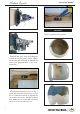
WWW.SEAGULLMODELS.COM 3x10mm 1) Slide the fiberglass cowl over the engine and line up the back edge of the cowl with the marks you made on the fuselage then trim and cut as shown. 3) Install the muffler and muffler extension onto the engine and make the cutout in the cowl for muffler clearance. Connect the fuel and pressure lines to the carburetor, muffler and fuel filler valve. Secure the cowl to fuselage using the M3x10mm screws.
Westland Lysander Instruction Manual. ELECTRIC POWER CONVERSION. 1) Locate the items necessary to installl the electric power conversion included with your model. M5x35mm 2) Recommend the items necessary to install the electric power conversion parts included with your model. - Motor: 50cc - Propeller: 22x10 ~ 26x12 - ESC: 120A - Lipo: 9S -15S 3) Attach the electric motor box to the firewall suitable with the cross lines drawn on the electric motor box and firewall.
WWW.SEAGULLMODELS.COM Blind nut. 4) Attach the motor to the front of the electric motor box using four 4mm blind nut, four M4x20mm hex head bolts to secure the motor. Please see picture shown. M4x20mm INSTALLING THE SPINNER. 5) Attach the speed control to the side of the motor box using two-sided tape and tie wraps. Connect the appropriate leads from the speed control to the motor. Make sure the leads will not interfere with the operation of the motor.
Westland Lysander Instruction Manual. 2) Place the servo between the mounting blocks and space it from the hatch. Use a pencil to mark the mounting hole locations on the blocks. INSTALLING THE AILERON SERVOS. 3) Use drill bit in a pin vise to drill the mouting holes in the blocks. Servos . Small weight . 4) Apply 2-3 drops of thin C/A to each of the mounting holes. Allow the C/A to cure without using accelerator.
WWW.SEAGULLMODELS.COM 6) Secure the servo to the aileron hatch using Phillips screwdriver and the screws provided with the servo. 7) Apply 1-2 drops of thin C/A to each of the mounting tabs. Allow the C/A to cure without using accelerator. . C/A glue 8) A string has been provided in the wing to pull the aileron lead through to the wing root. Remove the string from the wing at the servo location and use the tape to attach it to the servo extension lead.
Westland Lysander Instruction Manual. FLAP PUSHROD HORN INSTALLATION. 50mm INSTALLING THE FLAP SERVOS. INSTALLING THE RUDDER SERVO. The process as aileron servo to install servos for rudder. AILERON PUSHROD HORN INSTALLATION. 60mm M3 clevis. M3 lock nut. 2x10mm Metal clevis. Hex nut. Fuel tubing.
WWW.SEAGULLMODELS.COM INSTALLING THE ELEVATOR SERVO. Please see below pictures. Collar. Collar. WHEELS AND WHEEL PANTS. Please see these below pictures.
Westland Lysander Instruction Manual. Epoxy. 4x10mm INSTALLING THE MAIN LANDING GEAR.
WWW.SEAGULLMODELS.COM INSTALLING HORIZONTAL STABILIZER. INSTALLING RUDDER HINGE. The rudder hinge assembly as below pictures.
Westland Lysander Instruction Manual. 3x12mm Elevator control horn. Horizontal Stabilizer. 90º Vertical Stabilizer. 3) Thread one clevis and M3 lock nut on to each elevator control rod. Thread the horns on until they are flush with the ends of the control rods. 4) Elevator and rudder pushrods assembly as pictures below. 150mm M3 clevis. M3 lock nut. ELEVATOR PUSHROD HORN INSTALLATION. 1) Locate items necessary to install rudder pushrod.
WWW.SEAGULLMODELS.COM RUDDER PUSHROD HORN INSTALLATION. Locate items necessaryto install rudder pushrod. 115mm M3 clevis. M3 lock nut. Rudder pushrod. 1 Crimp. M3 clevis. MOUNTING THE TAIL WHEEL. Metal connector. Cable end. 2 Tail gear. 2 Collar.
Westland Lysander Instruction Manual. C/A glue. INSTALLATION PILOT AND CANOPY. . Locate items necessary to install pilot, 1) seats. 2) A scale pilot is included with this ARF. The Seagull Pilot included fitting well to the cockpit. (or you can order others scale pilot figures made by Seagull factory. They are available at Seagull distributors.) If you are going to install a pilot figure, please use a sanding bar to sand the base of the figure so that it is flat.
WWW.SEAGULLMODELS.COM 3) Position the pilot figure on the canopy floor as show. Locate the oval shaped on the canopy floor and remove the covering. Use epoxy to glue this into the base of the pilot figure and glue the cockpit panel in place with C/A glue, please see pictures as shown. C/A glue. Epoxy. 15mm 4) Position the canopy onto the fuselage. Trace around the canopy and onto the fuselage using a felt-tipped pen. Cut. C/A glue. 2x6mm APPLY THE DECALS.
Westland Lysander Instruction Manual. INSTALLING BATTERY - RECEIVER. 1) Plug the five servo leads and the switch lead into the receiver. Plug the battery pack lead into the switch also. 2) Wrap the receiver and battery pack in the protective foam rubber to protect them from vibration. Battery. Receiver. Battery. ATTACHMENT WING- FUSELAGE. Attach the aluminum tube into fuselage. Wing tube. 4x15mm Insert two wing panels as pictures below. Wing bolt.
WWW.SEAGULLMODELS.COM INSTALLING STRUT WING-FUSELAGE.
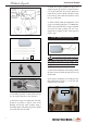
Westland Lysander Instruction Manual. BALANCING. 1) It is critical that your airplane be balanced correctly. Improper balance will cause your plane to lose control and crash. THE CENTER OF GRAVITY IS LOCATED 27MM FORWARD OF THE LEADING EDGE. 2) If the nose of the plane falls, the plane is nose heavy. To correct this first move the battery pack further back in the fuselage.
WWW.SEAGULLMODELS.
Westland Lysander Instruction Manual. FLIGHT PREPARATION. PREFLIGHT CHECK. Check the operation and direction of the elevator, rudder, ailerons and throttle. 1) Completely charge your transmitter and receiver batteries before your first day of flying. A) Plug in your radio system per the manufacturer’s instructions and turn everything on. 2) Check every bolt and every glue B) Check the elevator first. Pull back on the elevator stick. The elevator halves should move up.