A S S E M B LY M A N UA L RED BARON PIZZA SQUADRON’S STEARMAN 71. 5 i n ch e s . “ Graphics and specifications may change without notice ” . Code: SEA277 Specifications: Wingspan---------------71.5 in (181.6 cm). Wing area---------------1438.4 sq.in ( 92.8 sq.dm). Weight-------------------13.9 lbs (6.0- 6.3 kg). Length-------------------53.5 in (136 cm). Engine-------------------20cc gasoline. Radio--------------------5 channels with 6 servos.
Instruction Manual. STEARMAN 71.5 inches INTRODUCTION. Thank you for choosing the STEARMAN 71.5 inches ARF by SG MODELS . The STEARMAN 71.5 inches was designed with the intermediate/advanced sport flyer in mind. It is a semi scale airplane which is easy to fly and quick to assemble. The airframe is conventionally built using balsa, plywood to make it stronger than the average ARF, yet the design allows the aeroplane to be kept light. You will find that most of the work has been done for you already.
KIT CONTENTS. SEA277 STEARMAN 71.5 inches 1. Fuselage 2. Upper wing set 3. Lower wing set 4. Tail set 5. Cowling 6. Aluminum wing tube 7. Windshield and pilot 8. Wheel pants HINGING THE AILERON. Note : The control surfaces, including the ailerons, elevators, and rudder, are prehinged with hinges installed, but the hinges are not glued in place. It is imperative that you properly adhere the hinges in place per the steps that follow using a high-quality thin C/A glue.
STEARMAN 71.5 inches 4) Deflect the aileron and completely saturate each hinge with thin C/A glue. The ailerons front surface should lightly contact the wing during this procedure. Ideally, when the hinges are glued in place, a 1/64” gap or less will be maintained throughout the lengh of the aileron to the wing panel hinge line. Instruction Manual. 8) After both ailerons are securely hinged, firmly grasp the wing panel and aileron to make sure the hinges are securely glued and cannot be pulled out.
INSTALLING THE AILERON SERVOS. 3) Apply 2-3 drops of thin C/A to each of the mounting holes. Allow the C/A to cure without using accelerator. . . C/A glue Because the size of servos differ, you may need to adjust the size of the precut opening in the mount. The notch in the sides of the mount allow the servo lead to pass through. 1) Place the servo between the mounting blocks and space it from the hatch. Use a pencil to mark the mounting hole locations on the blocks.
STEARMAN 71.5 inches Instruction Manual. C/A glue 7) Remove the string from the wing at the servo location and use the tape to attach it to the servo extension lead. Pull the lead through the wing and remove the string. 8) Set the aileron hatch in place and use a Phillips screw driver to install it with four wood screws. M2x10mm AILERON PUSHROD INSTALLATION. Please see below pictures.
THROTTLE SERVO ARM INSTALLATION. 55mm M3 clevis. M3 lock nut. Install adjustable servo connector in the servo arm as same as picture below: Loctite secure. Adjustable servo connector. Servo arm. Elevator servo arm. Throttle servo arm. Rudder servo arm. INSTALLING THE FUSELAGE .SERVOS. Because the size of servos differ, you may need to adjust the size of the precut . opening in the mount. The notch in the sides of the mount allow the servo lead to pass through.
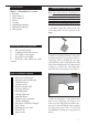
Instruction Manual. STEARMAN 71.5 inches . Switch. INSTALLING THE ENGINE SWITCH. Trim and cut. Switch. INSTALLING THE MAIN LANDING GEAR TO FUSELAGE.
Thread a mounting screw into each of the holes to cut threads in the surrounding wood. Apply a small amount of thin CA to harden the threads make by the screws. Position the landing gear so it rakes forward. Use the screws and landing gear straps to secure the landing gear to the bottom of the fuselage.
STEARMAN 71.5 inches Instruction Manual.
M3x10mm 11
STEARMAN 71.5 inches Instruction Manual. M4x5mm Collar. INSTALLING THE STOPPER ASSEMBLY. Collar. 1) Using a modeling knife, carefully cut off the rear portion of one of the 3 nylon tubes leaving 1/2” protruding from the rear of the stopper. This will be the fuel pick up tube. 2) Using a modeling knife, cut one length of silicon fuel line. Connect one end of the line to the weighted fuel pick up and the other end to the nylon pick up tube.
6) When satisfied with the alignment of the stopper assembly tighten the 3 x 20mm machine screw until the rubber stopper expands and seals the tank opening. Do not overtighten the assembly as this could cause the tank to split. FUEL TANK INSTALLATION. You should mark which tube is the vent and which is the fuel pickup when you attach fuel tubing to the tubes in the stopper. Once the tank is installed inside the fuselage, it may be difficult to determine which is which. Vent tube. Fuel pick up tube.
Instruction Manual. STEARMAN 71.5 inches Blow through one of the lines to ensure the fuel lines have not become kinked inside the fuel tank compartment. Air should flow through easily. ENGINE MOUNT INSTALLATION. 1) Locate the items necessary to install the engine mount included with your model. . 4x30mm Vent tube. Fuel pick up tube. Fuel fill tube. 9) Connect the lines from the tank to the engine and muffler. The vent line will connect to the muffler and the line from the clunk to the carburetor.
MOUNTING THE ENGINE. 1) Position the engine with the drive washer (145mm) forward of the firewall as shown. Machine screw M4x30mm 4) On the fire wall has the location for the throttle pushrod tube (pre-drill). 5) Slide the pushrod tube in the firewall and guide it through the fuel tank mount. Use medium C/A to glue the tube to the firewall and the fuel tank mount. 145mm 2) Use a pin drill and 4mm drill bit to drill a small indentation in the mount for the engine mounting screw.
STEARMAN 71.5 inches Instruction Manual. 8) Reinstall the servo horn by sliding the connector over the pushrod wire. Center the throttle stick and trim and install the servo horn perpendiular to the servo center line. 9) Move the throttle stick to the closed position and move the carburetor to closed. Use a 2.5mm hex wrench to tighten the screw that secures the throttle pushrod wire. Make sure to use threadlock on the screw so it does not vibrate loose.
DUMMY ENGINE. COWLING. Epoxy 1) Tape the cowl to the fuselage using low-tack tape. 2) Use a drill and drill bit to drill the holes for the cowl mounting screws. Make sure the cowl position is correct before drilling each hole.
STEARMAN 71.5 inches Instruction Manual. ELECTRIC POWER CONVERSION. 3x10mm 1) Locate the items neccessary to install the electric power conversion included with your model. Because of the size of the cowl, it may be necessary to use a needle valve extension for the high speed needle valve. Make this out of sufficient length 1.5mm wire and install it into the end of the needle valve. Secure the wire in place by tightening the set screw in the side of the needle valve.
Then, use 5.5mm drill bit to enlarge the holes on the electric motor box. 5.5mm M4x20mm Blind nut. 4) Attach the motor to the front of the electric motor box using four 4mm blind nut, four M4x20mm hex head bolts to secure the motor. Please see picture shown.
Instruction Manual. STEARMAN 71.5 inches Balsa stick. Epoxy 5) Attach the speed control to the side of the motor box using two-sided tape and tie wraps. Connect the appropriate leads from the speed control to the motor. Make sure the leads will not interfere with the operation of the motor. Speed control. Open the air exit hole. Battery.
INSTALLING THE SPINNER. INSTALL ELEVATOR CONTROL HORN. Install the spinner backplate, propeller and spinner cone. Fiberglass control horn The propeller should not touch any part of the spinner cone. If it does, use a sharp modeling knife and carefully trim away the spinner cone where the propeller comes in contact with it. Epoxy. Elevator fiberglass control horn. Epoxy. INSTALLING THE HORIZONTAL STABILIZER. HINGING THE ELEVATORS.
STEARMAN 71.5 inches Instruction Manual. 2) Using a modeling knife, carefully remove the covering at mounting slot of horizontal stabilizer ( both side of fuselage). Cut. 3) Slide the stabilizer into place in the precut slot in the rear of the fuselage. The stabilizer should be pushed firmly against the front of the slot. Trim and cut When cutting through the covering to remove it, cut with only enough pressure to only cut through the covering itself. Cutting into the balsa structure may weaken it.
Epoxy. . HINGING THE RUDDER. Glue the two rudder hinges in place using the same techniques used to hinge the ailerons. Rudder fiberglass control horn. INSTALLING VERTICAL STABILIZER INSTALL RUDDER CONTROL HORN. Repeat steps to install the rudder control horn as same as steps done for ailerons. Fiberglass control horn 1) Using a modeling knife, remove the covering from over the precut hinge slot cut into the lower rear portion of the fuselage.
Instruction Manual. STEARMAN 71.5 inches Fill Epoxy 2) While holding the vertical stabilizer firmly in place, use a pen and draw a line on each side of the vertical stabilizer where it meets the top of the fuselage. 5) When you are sure that everything is aligned correctly, mix up a generous amount of Flash 30 Minute Epoxy. Apply epoxy to the bottom and top edges of the filler block. Set the stabilizer in place and realign. Double check all of your measurements once more before the epoxy cures.
4) Elevator and rudder pushrods assembly as pictures below. RUDDER PUSHROD INSTALLATION. Repeat steps as same as steps done for elevator. 530mm M2 clevis. 543mm M2 lock nut. M2 clevis. M2 lock nut.
STEARMAN 71.5 inches Instruction Manual. MOUNTING THE TAIL WHEEL. Locate items necessary to imstall tail gear. Metal clevis. 482mm Nose wheel steering arm. M2 clevis. 26 M2 lock nut.
C/A glue. INSTALL BRACING WIRE AND METAL BRACKET AT THE TAIL. TOP VIEW.
STEARMAN 71.5 inches BOTTOM VIEW 3x15mm 28 Instruction Manual.
3x12mm 2) Place the cabane struts in position, noting their position as shown in the photo. Loosely install the four M3 x 12 socket head machine screws and M3 washers. Leave the hardware loose so the struts can be positioned while installing the upper wing center rib. Make sure to use threadlock on the screws so they won’t vibrate loose. CABANE STRUT INSTALLATION. NOTE : This is temporary steps for installing screws, so no need to tighten the screws..
Instruction Manual. STEARMAN 71.5 inches ATTACHMENT WING- FUSELAGE. Attach the aluminium tube into fuselage. Wing tube. 3) Place the upper center wing rib in position on the cabane struts. Start the M3 x 12 socket head machine screws and M3 washers that secure the rib to the cabane struts. Insert two lower wing panels as pictures below.
Insert two upper wing panels as pictures below. 2) Attach the two wing struts to the top of lower wing pant using an M3x12mm nachine screw and M3 washers. 4x12mm M3x12mm INSTALLATION WING STRUTS. 1) Loacte the items for this section of the manual.
STEARMAN 71.5 inches Instruction Manual. M3x12mm At this time, exact position of the end is set, please Use a 2.5mm hex wrench to slowly tighten the hardware securing the cabane struts in position on the fuselage. Again, make sure to use threadlock on all the fasteners to prevent them from vibrating loose. Repeat steps to prepare the remaining wing panel for installation.
INSTALLATION CABLE. 1) Prepare one end of the cable by attaching a cable end using a copper crimp. Thread a nut, then a clevis, on the cable end as shown. Prepare only one end of each cable at this time. Crimp M3 clevis Metal Cable. M3x30mm 2)Attach the clevis to the brass tab next to the rear interplane strut on the upperlower wing.Slide a copper crimp on the cable. Pass the cable through the brass tab on the upper wing, the back through the copper crimp.
Instruction Manual. STEARMAN 71.5 inches Using the transport frames allow the removal of the wings without the need to remove the aileron linkage and the interplane strut between the top and bottom wings. INSTALLATION PILOT AND WINDSHIELD. 1) Locate items necessary to install pilot and windshield. . 2) Use a 2.5mm hex wrench to remove the screws that attach the panels to the fuselage and center section. Slide the panels from the tubes and disconnect the servo lead for the aileron servo.
Epoxy. Epoxy. 4) Position the windshield onto the fuselage. Trace around the windshield onto the fuselage using a felt-tipped pen. Cut and remove the covering from between the lines drawn, and glue the windshield to the fuselage using epoxy or a special canopy glue. Epoxy.
Instruction Manual. STEARMAN 71.5 inches APPLY THE DECALS. BALANCING. 1) If all the decals are precut and ready to stick. Please be certain the model is clean and free from oily fingerprints and dust. Position decal on the model where desired, using the photos on the box and aid in their location. 1) It is critical that your airplane be balanced correctly. Improper balance will cause your plane to lose control and crash.
*If possible, first attempt to balance the model by changing the position of the receiver battery and receiver. If you are unable to obtain good balance by doing so, then it will be necessary to add weight to the nose or tail to achieve the proper balance point. 100mm CONTROL THROWS.
STEARMAN 71.5 inches Instruction Manual. FLIGHT PREPARATION. PREFLIGHT CHECK. Check the operation and direction of the elevator, rudder, ailerons and throttle. 1) Completely charge your transmitter and receiver batteries before your first day of flying. A) Plug in your radio system per the manufacturer’s instructions and turn everything on. 2) Check every bolt and every glue joint in the STEARMAN 71.5 INCHES to ensure that everything is tight and well bonded. B) Check the elevator first.
If you have any queries, or are interested in our products, please feel free to contact us Factory : 12/101A - Hamlet 4 - Le Van Khuong Street - Dong Thanh Ward Hoc Mon District - Ho Chi Minh City - Viet Nam. Office : 62/8 Ngo Tat To Street - Ward 19 - Binh Thanh District - Ho Chi Minh City - Viet Nam Phone : 848 - 37114542 or 848- 36018777 Website : www.SeagullModels.com Email : Sales@seagullmodels.com Facebook : www.facebook.com/SeaGullModels.