
User Manual

13
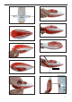
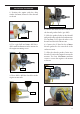
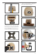
3) Carefully bend the second nylon tube up
at a 45º angle. is tube is the vent tube.
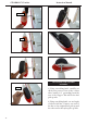
4) Test t the stopper assembly into the tank.
It may be necessary to remove some of the
ashing around the tank opening using a
modeling knife. If ashing is present, make
sure none falls into the tank.
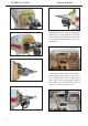
Vent tube.
Fuel pick up tube.
Fuel fill tube.
5) With the stopper assembly in place, the
weighted pick-up should rest away from the
rear of the tank and move freely inside the
tank. e top of the vent tube should rest just
below the top of the tank. It should not touch
the top of the tank.
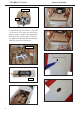
6) When satised with the alignment of the
stopper assembly tighten the 3 x 20mm ma-
chine screw until the rubber stopper expands
and seals the tank opening. Do not over-
tighten the assembly as this could cause the
tank to split.
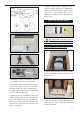
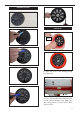
FUEL TANK INSTALLATION.
You should mark which tube is the vent
and which is the fuel pickup when you attach
fuel tubing to the tubes in the stopper. Once the
tank is installed inside the fuselage, it may be
dicult to determine which is which.
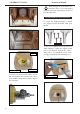
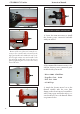
7) Slide the fuel tank into the fuselage. Guide
the lines from the tank through the hole in
the rewall.
8) Use balsa block to hold in place the fuel
tank with C/A glue to secure the fuel tank
inside the fuselage.