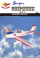
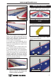
SIZE 55 ASSEMBLY MANUAL MS:120 “Graphics and specifications may change without notice”. Specifications: Wing span ------------------------------63in (160cm). Wing area -----------------643.3sq.in (41.5sq dm). Weight ------------------------7.9lbs (3.6kg). Length ------------------------------52.7in (133.8cm). Engine ------------------ 0.55cu.in ---- 2-stroke. 0.72cu.in ---- 4-stroke. Radio -------------------5 channels with 7 servos. Electric conversion: optional Flying skill level intermediate/advanced.
SUPER CHIPMUNK SIZE 55. Instruction Manual. INTRODUCTION. Thank you for choosing the SUPER CHIPMUNK SIZE 55 ARTF by SEAGULL MODELS COMPANY LTD. The SUPER CHIPMUNK SIZE 55 was designed with the intermediate/advanced sport flyer in mind. It is a semi scale airplane which is easy to fly and quick to assemble. The airframe is conventionally built using balsa, plywood to make it stronger than the average ARTF , yet the design allows the aeroplane to be kept light.
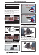
www.seagullmodels.com HINGING THE FLAP. KIT CONTENTS.TS 1 2 3 4 5 6 7 8 9 10 11 Fuselage Wing Set Tail Set Canopy Cowling Wing Tube Pilot Fiberglass Wheel Pants Landing Gear Tail Wheel Hardware Set ADDITIONAL ITEMS REQUIRED. 0.55 - 0.72 2-4--stroke. Computer radio with 7 servos. Glow plug to suit engine. Propeller to suit engine. Protective foam rubber for radio system. Silicone fuel line. Drill 1mm. TOOLS & SUPPLIES NEEDED. Thick cyanoacrylate glue. 30 minute epoxy. 5 minute epoxy.
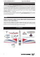
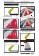
SUPER CHIPMUNK SIZE 55. Instruction Manual. 3) Slide the aileron on the wing panel until there is only a slight gap. The hinge is now centered on the wing panel and aileron. Remove the T-pins and snug the aileron against the wing panel. A gap of 1/64” or less should be maintained between the wing panel and aileron. Hinge. HINGING THE AILERONS . Note: The control surfaces, including the ailerons, elevators, and rudder, are prehinged with hinges installed, but the hinges are not glued in place.
www.seagullmodels.com HINGING THE ELEVATOR. Glue the rudder hinges in place using the same techniques used to hinge the ailerons. INSTALL THE AILERONS CONTROL HORN. 1) Locate the hardware necessary to install the control horns for the ailerons. 5) Turn the wing panel over and deflect the aileron in the opposite direction from the opposite side. Apply thin C/A glue to each hinge, making sure that the C/A penetrates into both the aileron and wing panel.
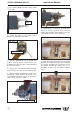
SUPER CHIPMUNK SIZE 55. INSTALL THE FLAP CONTROL HORN. Instruction Manual. Position the Control horn on the Aileron and use 30-minute Epoxy 1) Locate the hardware necessary to install the control horns for the ailerons. Fiberglass control horn. Epoxy. 2)Position the Control horn on the Aileron and use 30-minute Epoxy Elevator control horn. Epoxy. INSTALL RUDDER CONTROL HORN. Repeat steps to install the rudder control horn as same as steps done for ailerons. Fiberglass control horn.
www.seagullmodels.com Rudder control horn. ENGINE MOUNT INSTALLATION. 1) Locate the items necessary to install the engine mount included with your model. . 4x30mm. 2) Use four 4x30mm head bolts and four 4mm washers to attach the engine mount rails to the firewall. Tighten the screws . Make sure to use threadlock on the screws to help prevent them from vibrating loose. A. B. Vent tube. INSTALLING THE STOPPER ASSEMBLY.
SUPER CHIPMUNK SIZE 55. 4) Test fit the stopper assembly into the tank. It may be necessary to remove some of the flashing around the tank opening using a modeling knife. If flashing is present, make sure none falls into the tank. Instruction Manual. 8) Use plywood template to hold in place the fuel tank with C/A glue to secure the fuel tank inside the fuselage. 5) With the stopper assembly in place, the weighted pick-up should rest away from the rear of the tank and move freely inside the tank.
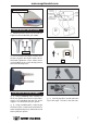
www.seagullmodels.com INSTALLING THE FUSELAGE SERVOS. Because the size of servos differ, you may need to adjust the size of the precut opening in the mount. The notch in the sides of the mount allow the servo lead to pass through. 1) Install the rubber grommets and brass collets onto the throttle servo. Test fit the servo into the aileron servo mount. Trim and cut. 2) Secure the servos with the screws provided with your radio system. Throttle servo. Rudder servo. Switch. Elevator servo.
SUPER CHIPMUNK SIZE 55. Instruction Manual. 3) Use a drill to drill the four holes in the engine mount rails. 2mm. 8) Reinstall the servo horn by sliding the connector over the pushrod wire. Center the throttle stick and trim and install the servo horn perpendicular to the servo center line. 4) On the fire wall has the location for the throttle pusshrod tube (pre-drill). Drill 4mm. Pushrod tube hole. 5) Slide the pushrod tube in the firewall and guide it through the fuel tank mount.
www.seagullmodels.com COWLING. 1)Slide the fiberglass cowl over the engine and line up the back edge of the cowl with the marks you made on the fuselage then trim and cut as shown. 2) While keeping the back edge of the cowl flush with the marks, align the front of the cowl with the crankshaft of the engine. The front of the cowl should be positioned so the crankshaft is in nearly the middle of the cowl opening. Use the spinner backplate as a guide.
SUPER CHIPMUNK SIZE 55. ELECTRIC POWER CONVERSION. 1) Locate the items neccessary to install the electric power conversion included with your model. Instruction Manual. 3) Attach the motor to the front of the electric motor box using four 3mm blind nut, four M3x15mm hex head bolts to secure the motor. Please see picture shown. 4mm. Recommendation EP parts as shown (not included with your model) - Model size: .
www.seagullmodels.com M3x15mm. 5) Attach the speed control to the side of the motor box using two-sided tape and tie wraps. Connect the appropriate leads from the speed control to the motor. Make sure the leads will not interfere with the operation of the motor. Speed control. Epoxy. INSTALLING THE SPINNER. Install the spinner backplate, propeller and spinner cone. 110mm. Balsa stick. Epoxy. Electric motor. The propeller should not touch any part of the spinner cone.
SUPER CHIPMUNK SIZE 55. Instruction Manual. INSTALLING THE AILERON - FLAP SERVOS. 3) Apply 2-3 drops of thin C/A to each of the mounting holes. Allow the C/A to cure without using accelerator. Servos. Small weight. Thread. Because the size of servos differ, you may need to adjust the size of the precut opening in the mount. The notch in the sides of the mount allow the servo lead to pass through. 4) Use dental floss to secure the connection so they cannot become unplugged.
www.seagullmodels.com 7) A string has been provided in the wing to pull the aileron lead through to the wing root. Remove the string from the wing at the servo location and use the tape to attach it to the servo extension lead. Pull the lead through the wing and remove the string. 9) Set the aileron hatch in place and use a Phillips screw driver to install it with four wood screws. M2x10mm. AILERON PUSHROD HORN INSTALLATION Mark. Pen.
SUPER CHIPMUNK SIZE 55. Instruction Manual. 1) Mark the control wire where it crosses the servo arm hole. FLAP PUSHROD HORN INSTALLATION Bend at the mark. 8mm. M2 lock nut. Cut. Metal clevis. 8mm Snap keeper. Servo arm. 2) Make a 90-degree bend at the mark and cut off the excess wire leaving 8mm past the bend. Snap keeper. M2 lock nut. Metal clevis. 8mm Snap keeper. Servo arm. Snap keeper. INSTALLING LANDING GEAR 3) Connect the linkage as shown and secure the control wire with a snap keeper.
www.seagullmodels.com 2)Install Spring Landing Gear into Wings. Pen. Plastic plate. Wheel Pant. Drill 2mm. Drill 1.5mm. Landing Gear. M2x10mm. M3x15mm.
SUPER CHIPMUNK SIZE 55. Instruction Manual. 3)Install Wheels into Fiberglass Wheels Pants. Washer. Wheel . Epoxy. 4)Attach Fiberglass Wheel Pants into landing Gear. Drill hole M3x10mm. Alxe. Wheel collar. Alxe.
www.seagullmodels.com INSTALLING THE HORIZONTAL STABILIZER. 1) Using a ruler and a pen, locate the centerline of the horizontal stabilizer, at the trailing edge, and place a mark. Use a triangle and extend this mark, from back to front, across the top of the stabilizer. Also extend this mark down the back of the trailing edge of the stabilizer. 4) With the stabilizer held firmly in place, use a pen and draw lines onto the stabilizer where it and the fuselage sides meet.
SUPER CHIPMUNK SIZE 55. 7) When you are sure that everything is aligned correctly, mix up a generous amount of 30 Minute Epoxy. Apply a thin layer to the top and bottom of the stabilizer mounting area and to the stabilizer mounting platform sides in the fuselage. Slide the stabilizer in place and realign. Double check all of your measurements once more before the epoxy cures. Hold the stabilizer in place with T-pins or masking tape and remove any excess epoxy using a paper towel and rubbing alcohol.
www.seagullmodels.com M3x12mm. MOUNTING THE TAIL WHEEL. 1) Locate the items for this section of the manual. Platic part. Cut. C/A glue.
SUPER CHIPMUNK SIZE 55. HINGING THE RUDDER. Glue the rudder hinges in place using the same techniques used to hinge the ailerons. Instruction Manual. ELEVATOR PUSHROD HORN INSTALLATION. 1) Install the elevator control horn using the same method as with the aileron control horns. 2) Position the elevator control horn on the both side of elevator. Epoxy. Elevator control horn. Elevator control horn. 3) Thread one clevis and M2 lock nut on to each elevator control rod.
www.seagullmodels.com Control horn. Pen. Metal clevis. Elevator pushrod. M2 lock nut. Elevator pushrod. 8mm. Wire keeper. 8mm. 8mm. RUDDER PUSHROD HORN INSTALLATION. M2 lock nut . M2 clevis. 8mm.
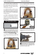
SUPER CHIPMUNK SIZE 55. Instruction Manual. Rudder pushrod. Metal clevis. Control horn. M2 lock nut. M2x6mm. Elevator pushrod. 2) A scale pilot is included with this ARF. The Seagull Pilot included fitting well to the cockpit. (or you can order others scale pilot figures made by Seagull factory. They are available at Seagull distributors.) Pen. If you are going to install a pilot figure, please use a sanding bar to sand the base of the figure so that it is flat.
www.seagullmodels.com C/A glue. Wing tube. M2x6mm. APPLY THE DECALS. 1) If all the decals are precut and ready to stick. Please be certain the model is clean and free from oily fingerprints and dust. Position decal on the model where desired, using the photos on the box and aid in their location. Insert two wing panels as pictures below. 2) If all the decals are not precut, please use scissors or a sharp hobby knife to cut the decals from the sheet.
SUPER CHIPMUNK SIZE 55. M4x20mm. Instruction Manual. Accurately mark the balance point on the top of the wing on both sides of the fuselage. The balance point is located 88mm back from the leading edge of the wing at the wing root. This is the balance point at which your model should balance for your first flights. Later, you may wish to experiment by shifting the balance up to 10mm forward or back to change the flying characteristics.
www.seagullmodels.com CONTROL THROWS.
SUPER CHIPMUNK SIZE 55. Instruction Manual. FLIGHT PREPARATION. PREFLIGHT CHECK. Check the operation and direction of the elevator, rudder, ailerons and throttle. 1) Completely charge your transmitter and receiver batteries before your first day of flying. A) Plug in your radio system per the manufacturer's instructions and turn everything on. B) Check the elevator first. Pull back on the elevator stick. The elevator halves should move up.