
User Manual


WWW.SEAGULLMODELS.COM
15
Epoxy.
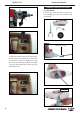
Because of the size of the cowl, it may be nec-
essary to use a needle valve extension for the
high speed needle valve. Make this out of suf-
cient length 1.5mm wire and install it into
the end of the needle valve. Secure the wire in
place by tightening the set screw in the side of
the needle valve.
.
2) While keeping the back edge of the cowl
ush with the marks, align the front of the
cowl with the cranksha of the engine. e
front of the cowl should be positioned so the
cranksha is in nearly the middle of the cowl
opening. Use the spinner backplate as a
guide. Hold the cowl rmly in place using
pieces of masking tape.
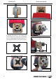
3) Install the muer and muer extension
onto the engine and make the cutout in the
cowl for muer clearance. Connect the fuel
and pressure lines to the carburetor, muer
and fuel ller valve. Secure the cowl to fuse-
lage using the M3x10mm screws.
Needle valve
Machine screw M3x10mm
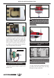
ELECTRIC POWER CONVERSION.
1) Locate the items neccessary to install
the electric power conversion included
with your model.
2) Recommendation EP parts as shown
(not included with your model).
- Model size: .60 size models
- Motor: 50mm 310 rev per volt
- Propeller: 14x10 ~ 15x10
- ESC: 60A
- Lipo Batteries: 8 cell 5200mA
3) Attach the electric motor box to the
rewall suitable with the cross lines
drawn on the electric motor box and
rewall. Using epoxy and balsa stick
to secure the motor box to the rewall.
Please see pictures below.