MS:180 ASSEMBLY MANUAL “Graphics and specifications may change without notice”. Specifications: Wing span ------------------------------79.9in (203cm). Wing area -----------------922.3sq.in (59.5sq dm). Weight ------------------------7.9-8.8lbs (3.6-4.0kg). Length ------------------------------50.0in (127.0cm). Engine ------------------ 0.61-0.75cu.in -----2-stroke. 0.91.in -----4-stroke. Radio ------------------- 5 channels with 7 servos.
Instruction Manual. CHRISTEN HUSKY INTRODUCTION. Thank you for choosing the CHRISTEN HUSKY ARTF by SEAGULL MODELS COMPANY LTD. The CHRISTEN HUSKY was designed with the intermediate/advanced sport flyer in mind. It is a semi scale airplane which is easy to fly and quick to assemble. The airframe is conventionally built using balsa, plywood to make it stronger than the average ARTF , yet the design allows the aeroplane to be kept light. You will find that most of the work has been done for you already.
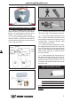
www.seagullmodels.com KIT CONTENTS.TS HINGING THE FLAP SEA180 CHRISTEN HUSKY 2030mm SEA18001 Fuselage SEA18002 Wing set SEA18003 Tail set SEA18004 Cowling : SEA18005 Main Landing Gear SEA18006 Tail Gear SEA18007 Windshield Set SEA18008 Decal Set SEA18009 Linkage Set SEA18010 Wing Tube SEA18011 Fiberglass Wheel pants ZZBSEA180B Replacement Box FL180 Floating set for Christen Husky ADDITIONAL ITEMS REQUIRED. 0.61- 0.75 0.91 2-stroke. 4-stroke. M2x10mm. Computer radio with 7 servos.
? CHRISTEN HUSKY Instruction Manual. 3) Remove each hinge from the horizontal stabilizer panel and elevator and place a Tpin in the center of each hunge. Slide each hinge into the elevator until the T-pin is snug against the elevator. This will help ensure an equal amount of hinge is on either side of the hinge line when the elevator is mounted to the horizontal stabilizer panel. Epoxy HINGING THE ELEVATORS 1)Locate the items for this section of the manual.
www.seagullmodels.com HINGING THE RUDDER Glue the rudder hinges in place using the same techniques used to hinge the ailerons. Epoxy INSTALL THE . INSTALL THE AILERONS CONTROL HORN. Fiberglass Fiberglass control horn.
Instruction Manual. CHRISTEN HUSKY INSTALL ELEVATOR CONTROL HORN. Aileron control horn. Epoxy Fiberglass control horn. INSTALL FLAP CONTROL HORN. Install the flap control horn using the same method as same as the aileron control horns. Fiberglass control horn. Epoxy Flap control horn. INSTALL RUDDER CONTROL HORN. Epoxy Repeat steps to install the rudder control horn as same as steps done for ailerons. Fiberglass control horn.
www.seagullmodels.com wheel collar. Washer. Epoxy. Axle. M3. wheel. wheel. M3. wheel collar. Washer. nut. Axle. M3. M3. wheel Pant. Epoxy C/A glue. Rudder control horn. WHEEL AND WHEEL PANTS. 1)Assembling and muonting the wheel pants as shown below pictures. INSTALLING THE MAIN LANDING GEAR TO FUSELAGE. Axle Wheel collar.
Instruction Manual. CHRISTEN HUSKY Thread locker glue M4x20mm Locker glue. M4x20mm M4x20mm ENGINE MOUNT INSTALLATION. 1) Locate the items necessary to install the engine mount included with your model. . 4x30mm. INSTALLING WHEEL PANTS TO MAIN LADING GEAR. Landing Gear. 2) Use four 4x30mm head bolts and four 4mm washers to attach the engine mount rails to the firewall. Tighten the screws . Make sure to use threadlock on the screws to help prevent them from vibrating loose. wheel Pant. C/A glue.
www.seagullmodels.com Vent tube. INSTALLING THE STOPPER ASSEMBLY. 1) Using a modeling knife, carefully cut off the rear portion of one of the 3 nylon tubes leaving 1/2” protruding from the rear of the stopper. This will be the fuel pick up tube. 2) Using a modeling knife, cut one length of silicon fuel line. Connect one end of the line to the weighted fuel pick up and the other end to the nylon pick up tube. Fuel pick up tube. Fuel fill tube. 3) Carefully bend the second nylon tube up at a 45º angle.
Instruction Manual. CHRISTEN HUSKY A Vent tube. Fuel pick up tube. C/A glue. 7) Slide the fuel tank into the fuselage. Guide the lines from the tank through the hole in the firewall. Fuel fill tube. 9) Connect the lines from the tank to the engine and muffler. The vent line will connect to the muffler and the line from the clunk to the carburetor. 8) Use plywood template to hold in place the fuel tank with C/A glue to secure the fuel tank inside the fuselage. Fuel tank.
www.seagullmodels.com INSTALLING THE SWITCH. Install the switch into the precut hole in the side, in the fuselage. Throttle servo. 3/ 32” Hole. THROTTLE SERVO ARM INSTALLATION. Recomend mounting switch inside fuselage if using floats. Install adjustable servo connector in the servo arm as same as picture below: Loctite secure. Adjustable Servo connector. Servo arm. Cut Covering. 1 PCS. Throttle servo arm. Switch Installation. MOUNTING THE ENGINE.
Instruction Manual. CHRISTEN HUSKY 4) On the fire wall has the location for the throttle pusshrod tube (pre-drill). 145mm. Pushrod tube hole. 2) Use a pin drill and 4mm drill bit to drill a small indentation in the mount for the engine mounting screw. 4mm. 5) Slide the pushrod tube in the firewall and guide it through the fuel tank mount. Use medium C/A to glue the tube to the firewall and the fuel tank mount. 6) Connect the Z-bend in the 450mm throttle pushrod to the outer hole of the carburetor arm.
www.seagullmodels.com 9) Move the throttle stick to the closed position and move the carburetor to closed. Use a 2.5mm hex wrench to tighten the screw that secures the throttle pushrod wire. Make sure to use threadlock on the screw so it does not vibrate loose. Trim and cut. Trim and cut. COWLING. 1)Slide the fiberglass cowl over the engine and line up the back edge of the cowl with the marks you made on the fuselage then trim and cut as shown.
Instruction Manual. CHRISTEN HUSKY - Model size: .75-.90 size models Motor: 50mm 310 rev per volt Propeller: 14x10 ~ 15x10 ESC: 60A Lipo Batteries: 8 cell 3200mA 2) Attach the electric motor box to the firewall suitable with the cross lines drawn on the electric motor box and firewall. Using epoxy and balsa stick to secure the motor box to the firewall. Please see pictures below. 3) Install the muffler and muffler extension onto the engine and make the cutout in the cowl for muffler clearance.
www.seagullmodels.com Epoxy. 145mm. Balsa stick. 4mm. Epoxy. Electric motor. 4) Locate the plywood battery tray to the fuselage. Tighten the screws using machine screws M3x15mm to secure the tray in position. Blind nut. Battery. Tie wraps. M3x15mm.
Instruction Manual. CHRISTEN HUSKY 5) Attach the speed control to the side of the motor box using two-sided tape and tie wraps. Connect the appropriate leads from the speed control to the motor. Make sure the leads will not interfere with the operation of the motor. INSTALLING THE AILERON - FLAP SERVOS. Recomend Mounting Speed Control inside Fuselage If Flying off Water. Speed control. M3x15mm. Servos. Small weight. INSTALLING THE SPINNER. Install the spinner backplate, propeller and spinner cone.
www.seagullmodels.com C/A glue. 4) Apply 2-3 drops of thin C/A to each of the mounting holes. Allow the C/A to cure without using accelerator. 8) A string has been provided in the wing to pull the aileron lead through to the wing root. Remove the string from the wing at the servo location and use the tape to attach it to the servo extension lead. Pull the lead through the wing and remove the string. C/A glue. 5) Use dental floss to secure the connection so they cannot become unplugged.
CHRISTEN HUSKY 18 Instruction Manual.
www.seagullmodels.com Wing. M2 lock nut. Aileron. 9) Set the aileron hatch in place and use a Phillips screw driver to install it with four wood screws. INSTALLING THE FLAP SERVO Repeat the procedure for the aileron servo. 50 mm M2 clevis. M2 lock nut. M2x10mm Wing. M2 lock nut. AILERON PUSHROD HORN INSTALLATION 60mm. M2 clevis. M2 lock nut. Flag.
Instruction Manual. CHRISTEN HUSKY INSTALLING THE HORIZONTAL STABILIZER. 1) Using a ruler and a pen, locate the centerline of the horizontal stabilizer, at the trailing edge, and place a mark. Use a triangle and extend this mark, from back to front, across the top of the stabilizer. Also extend this mark down the back of the trailing edge of the stabilizer. Draw center line. 4) With the stabilizer held firmly in place, use a pen and draw lines onto the stabilizer where it and the fuselage sides meet.
www.seagullmodels.com 7) When you are sure that everything is aligned correctly, mix up a generous amount of 30 Minute Epoxy. Apply a thin layer to the top and bottom of the stabilizer mounting area and to the stabilizer mounting platform sides in the fuselage. Slide the stabilizer in place and realign. Double check all of your measurements once more before the epoxy cures. Hold the stabilizer in place with T-pins or masking tape and remove any excess epoxy using a paper towel and rubbing alcohol.
Instruction Manual. CHRISTEN HUSKY Rudder control horn. Epoxy. 4) When you are sure that everything is aligned correctly, mix up a generous amount of Flash 30 Minute Epoxy. Apply a thin layer to the mounting slot and to bottom of the vertical stabilizer mounting area. Apply epoxy to the bottom and top edges of the filler block and to the lower hinge also. Set the stabilizer in place and realign. Double check all of your measurements once more before the epoxy cures.
www.seagullmodels.com INSTALLATION TAILWHEEL. 1) Locate the items for this section of the manual.
Instruction Manual. CHRISTEN HUSKY 3x25 mm. Aluminum tail landing gear. 3 x 20mm. 2) A scale pilot is included with this ARF. The Seagull Pilot included fitting well to the cockpit. (or you can order others scale pilot figures made by Seagull factory. They are available at Seagull distributors.) If you are going to install a pilot figure, please use a sanding bar to sand the base of the figure so that it is flat. INSTALLATION PILOT AND CANOPY. 1) Locate items necessary to install pilot, seats .
www.seagullmodels.com Receiver. Epoxy Battery. APPLY THE DECALS. 1) If all the decals are precut and ready to stick. Please be certain the model is clean and free from oily fingerprints and dust. Position decal on the model where desired, using the photos on the box and aid in their location. ATTACHMENT WING- FUSELAGE. Attach the aluminium tube into fuselage. Wing tube. 2) If all the decals are not precut, please use scissors or a sharp hobby knife to cut the decals from the sheet.
Instruction Manual. CHRISTEN HUSKY Epoxy. M3x15mm. 2 Screw. M4x20mm. M3x15mm. 1 M4x12mm. Screw. INSTALLATION STRUT WING-FUSELAGE.
www.seagullmodels.com OPTIONAL FLOAT FOR HUSKY. Install Structs onto floats 1 Screw. 2 4 3 M3x15mm.
Instruction Manual.
www.seagullmodels.com M2 clevis. M2 lock nut. 600mm.
Instruction Manual. CHRISTEN HUSKY C/A glue 4 x 20mm BALANCING. 1) It is critical that your airplane be balanced correctly. Improper balance will cause your plane to lose control and crash. THE CENTER OF GRAVITY IS LOCATED 60 MM BACK FROM THE LEADING EDGE OF THE WING AT THE WING ROOT. 2) Mount the wing to the fuselage. Using a couple of pieces of masking tape, place them on the bottom side of the wing 60=mm back from the leading edge of the wing at the wing root.
www.seagullmodels.com 3) With the model upright, place your fingers on the masking tape and carefully lift the plane. 1 4) Do not turn plane upside down. Only low wing models should be turned upsidedown for balancing. Remove this paragraph, it is not intended for use in the instructions. it is a note for you.High Wing models must be balanced upright. Accurately mark the balance point on the botttom of the wing on both sides of the fuselage.
CHRISTEN HUSKY FLIGHT PREPARATION. Instruction Manual. PREFLIGHT CHECK. Check the operation and direction of the elevator, rudder, ailerons and throttle. 1) Completely charge your transmitter and receiver batteries before your first day of flying. A) Plug in your radio system per the manufacturer's instructions and turn everything on. 2) Check every bolt and every glue joint in the CHRISTEN HUSKY to ensure that everything is tight and well bonded. B) Check the elevator first.