ASSEMBLY MANUAL MS: 60 Specifications Wingspan------------------------------------------- 59 in---------------------------- 150cm. Wing area------------------------------------- 645 sq.in------------------------ 42 sq.dm. Approximate flying weight--------------- 5.7-6.4lbs----------------------- 2.6-2.9kg. Length------------------------------------------------ 50 in--------------------------- 128cm. Recommended engine size--------- .46-.55 cu.in------------------------- 2-stroke. .72 cu.
EDGE 540 Instruction Manual INTRODUCTION. Thank you for choosing the EDGE 540 ARTF by SEAGULL MODELS. The EDGE 540 was designed with the intermediate/advanced sport flyer in mind. It is a scale airplane which is easy to fly and quick to assemble. The airframe is conventionally built using balsa, plywood to make it stronger than the average ARTF , yet the design allows the aeroplane to be kept light. You will find that most of the work has been done for you already.
www.seagullmodels.com NOTE: To avoid scratching your new aeroplane we suggest that you cover your workbench with an old towel. Keep a couple of jars or bowls handy to hold the small parts after you open the bags. Please trial fit all parts. Make sure you have the correct parts and that they fit and are aligned properly before gluing! This will ensure proper assembly as the EDGE 540 is made from natural materials and minor adjustments may have to be made.
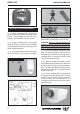
EDGE 540 Instruction Manual HINGING THE AILERONS. Note: The control surfaces, including the ailerons, elevators, and rudder, are prehinged with hinges installed, but the hinges are not glued in place. It is imperative that you properly adhere the hinges in place per the steps that follow using a high-quality thin C/A glue. 1) Carefully remove the aileron from one of the wing panels. Note the position of the hinges.
www.seagullmodels.com 6) Using C/A remover/debonder and a paper towel, remove any excess C/A glue that may have accumulated on the wing or in the aileron hinge area. 7) Repeat this process with the other wing panel, securely hinging the aileron in place. 8) After both ailerons are securely hinged, firmly grasp the wing panel and aileron to make sure the hinges are securely glued and cannot be pulled out. Do this by carefully applying medium pressure, trying to separate the aileron from the wing panel.
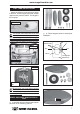
EDGE 540 Instruction Manual Vent tube. Fuel pick up tube. INSTALLING THE STOPPER ASSEMBLY. 1) Using a modeling knife, carefully cut off the rear portion of one of the 3 nylon tubes leaving 1/2” protruding from the rear of the stopper. This will be the fuel pick up tube. 2) Using a modeling knife, cut one length of silicon fuel line. Connect one end of the line to the weighted fuel pick up and the other end to the nylon pick up tube. 3) Carefully bend the second nylon tube up at a 45º angle.
www.seagullmodels.com FUEL TANK INSTALLATION. Attach the silicone fuel and pressure pipes to the tank. The lower pipe is the ‘feed’ and the upper two the ‘pressure and fill’. The fill pipe is the next pipe. Plastic tape. You should mark which tube is the vent and which is the fuel pickup when you attach fuel tubing to the tubes in the stopper. Once the tank is installed inside the fuselage, it may be difficult to determine which is which. 2) Follow diagram below for wheel pant installation: (2) Washer.
EDGE 540 Instruction Manual 3) You have to trim each axle using a tool cutting and cut-off wheel. Caution when cutting the axles and wear protective goggles. 46mm (2) Washer. (2) Wheel Collar. Axle. Wheel. Nut. Nut. 4) A drop of C/A glue on the wheel collar screws will help keep them from coming lose during operation. Repeat the process for the other wheel. Landing gear. INSTALLING THE MAIN LANDING GEAR. 1) The blind nuts for securing the landing gear are already mounted inside the fuselage.
www.seagullmodels.com 1.5mm. 4x20mm. MOUNTING THE ENGINE. 1) Install the pushrod housing through the predrilled hole in the firewall and into the servo compartment. The pushrod housing should protrude 1/4" out past the front of the firewall. Make a Z-Bend 1/4" from one end of the plain wire pushrod. 5) Bolt the engine to the engine mount using the four machine screws. Double check that all the screws are tight before proceeding.
EDGE 540 Instruction Manual COWLING INSTALLATION. 1) Slide the fiberglass cowl over the engine and line up the back edge of the cowl with the marks you made on the fuselage then trim and cut. 1.5mm wire (needle valve). 3x10mm. Trim and cut. 3) Install the muffler and muffler extension onto the engine and make the cut out in the cowl for muffler clearance. Connect the fuel and pressure lines to the carburetor, muffler and fuel filler valve. Secure the cowl to fuselage using the 3x10mm screws (4).
www.seagullmodels.com INSTALLING THE SPINNER. Install the spinner backplate, propeller and spinner cone. The propeller should not touch any part of the spinner cone. If it does, use a sharp modeling knife and carefully trim away the spinner cone where the propeller comes in contact with it. Remove covering. Switch. INSTALLING THE FUSELAGE SERVO. Because the size of servos differ, you may need to adjust the size of the precut opening in the mount.
EDGE 540 Instruction Manual HORIZONTAL STABILIZER. 1) Using a ruler and a pen, locate the centerline of the horizontal stabilizer, at the trailing edge, and place a mark. Use a triangle and extend this mark, from back to front, across the top of the stabilizer. Also extend this mark down the back of the trailing edge of the stabilizer. Center line. Pen. 5) Remove the stabilizer. Using the lines you just drew as a guide, carefully remove the covering from between them using a modeling knife.
www.seagullmodels.com 8) After the epoxy has fully cured, remove the masking tape or T-pins used to hold the stabilizer in place. Carefully inspect the glue joints. Use more epoxy to fill in any gaps that may exist that were not filled previously and clean up the excess using a paper towel and rubbing alcohol. Remove covering. 2) Slide the vertical stabilizer into the slot in the top of the fuselage.
EDGE 540 Instruction Manual When cutting through the covering to remove it, cut with only enough pressure to only cut through the covering itself. Cutting into the balsa structure may weaken it. INSTALLING THE AILERON SERVOS. Small weight. 5) Slide the vertical stabilizer back in place. Using a triangle, check to ensure that the vertical stabilizer is aligned 90º to the horizontal stabilizer. Servos. Horizontal Stabilizer. 90º Vertical Stabilizer.
www.seagullmodels.com Aileron electric. Plastic tape. Secure the servos with the screws provided with your radio system. Repeat the procedure for orther wing haft. AILERON CONTROL HORN INSTALLATION 2 sets. 3x40mm. Wing bottom. 1) Aileron control horn: Mix a small amount of 30 minute epoxy and lightly coat the inside of the hole in the aileron and the control horn screw. Wing. Aileron. Wing bottom. Wing panel bottom. Pu ll. String. Electric wire. drill hole 3.2mm.
EDGE 540 Instruction Manual M2 lock nut. Wing bottom. Repeat the procedure for the other wing. M3 lock nut. M3 control horn. ELEVATOR - RUDDER CONTROL HORN INSTALLATION. M3 nut. 1) Install the elevator control horn using the same method as with the aileron control horns. Aluminium washer. Wing bottom. 2) Position the elevator control horn on the both side of elevator. 2 sets. M2 clevis. M2 lock nut. Snap keeper. 3x35mm. Wing. Aileron. Aileron control horn. Wing bottom.
www.seagullmodels.com Elevator pushrod. Control horn. Elevator control horn. Clevis. Rudder pushrod. Right side. Left side. Elevator pushrod. Rudder control horn. Elevator control horn. Rudder pushrod. Elevator pushrod. Elevator. Rudder. Elevator. Throttle. ELEVATOR - RUDDER PUSHROD INSTALLATION. 1) Thread one clevis and M2 lock nut on to each elevator control rod. Thread the horns on until they are flush with the ends of the control rods.
EDGE 540 Instruction Manual INSTALLING TAIL STRUT SYSTEM. The tail strut system assembly follow pictures below. 3x10mm. Alumium trap. Alumium trap. 1 3x10cm(2pcs). Plastic clip. 2 Turnbuckle. 1 2 63mm. MOUNTING THE TAIL WHEEL. 1) Set the tail wheel assembly in place on the plywood plate. The pivot point of the tail wheel wire should be even with the rudder hinge line and the tail wheel bracket should be on the plywood plate.
www.seagullmodels.com 2) Using a pen, mark the locations of the two mounting screws. Remove the tail wheel bracket and drill 1mm pilot holes at the locations marked. Tie wrap. Tie wrap. Receiver. 3) Secure the tail wheel bracket in place using two 3x10mm wood screws. Be careful not to overtighten the screws. Battery. Antenna. MOUNTING THE CONTROL CLASP. See pictures below. ATTACHMENT WING-FUSELAGE. Attach the aluminium tube into fuselage. Control clasp. 2x20mm. 2 screws.
EDGE 540 Instruction Manual CONTROL THROWS. Wing bolt. 1) We highly recommend setting up the EDGE 540 using the control throws listed at right. We have listed control throws for both Low Rate (initial test flying/sport flying) and High Rate (aerobatic flying). 2) Turn on the radio system, and with the trim tabs on the transmitter in neutral, center the control surfaces by making adjustments to the clevises or adjustable servo connectors. The servo arms should be centered also.
www.seagullmodels.com D) Check the rudder. Looking from behind the airplane, move the rudder stick to the right. The rudder should move to the right. If it does not, flip the servo reversing switch on your transmitter to change the direction. E) Check the throttle. Moving the throttle stick forward should open the carburetor barrel. If it does not, flip the servo reversing switch on your transmitter to change the direction. F) From behind the airplane, look at the aileron on the right wing half.