
Home Security System User Manual


Appendix A: Modbus Communications User Guide: LDRA6
www.rletech.com 970 484-6510 16
APPENDIX A: MODBUS COMMUNICATIONS
This document describes the Modbus communications protocol as supported by the LDRA6. It includes
details and information on how to configure the LDRA6 for communications via Modbus network.
A-1 MODBUS IMPLEMENTATION OF THE LDRA6
The LDRA6 is capable of communicating via the half-duplex RS485 serial communication standard. The
LDRA6 is configured to act as a slave device on a common network. The RS485 medium allows for
multiple devices on a multi-drop network. The LDRA6 is a slave only device and will never initiate a
communications sequence.
A-1.1 Modes of Transmission
The Modbus protocol uses ASCII and RTU modes of transmission. The LDRA6 supports only the RTU
mode of transmission, with 8 data bits, even, odd or no parity and one stop bit.
Every Modbus packet consists of four fields:
Slave Address Field
Function Field
Data Field
Error Check Field (Checksum)
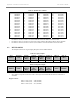
A-1.1.1 Slave Address Field
The slave address field is one byte in length and identifies the slave device involved in the transaction.
Valid address range is between 1 and 254. SW2 on the LDRA6 board sets the address. The firmware
program constantly reads dip SW2. Any changes are updated on the fly. Close the SW2 positions that
correspond to the binary number of the address.
A-1.1.2 Function Field
The function field tells the LDRA6 which function to perform. Function codes are designed to invoke a
specific action by the LDRA6.
A-1.1.3 Data Field
The data field varies in length depending on whether the message is a request or a response to a packet.
This field typically contains information required by the LDRA6 to perform the command specified or to
pass back data to the master device.
A-1.1.4 Error Check Field
The error check field consists of a 16-bit (2 byte) Cyclical Redundancy Check (CRC16). It allows the
LDRA6 to detect a packet that has been corrupted with transmission errors.