Image® 410 Laminator Owners Manual Owner’s Operation Manual Image ® 410 Laminator
TABLE OF CONTENTS TABLE OF CONTENTS ...................................................................................................................................................................2 INTRODUCTION................................................................................................................................................................................3 WORKSPACE / ELECTRICAL REQUIREMENTS .....................................................................................
INTRODUCTION Thank you for purchasing a SEAL ® Image® 410 Laminator. We have designed the SEAL Image 410 to give you years of reliable service. The Image 410 brings a new level of simplicity and ease of use to image finishing. As you become familiar with your laminator, you will appreciate the high quality of its production and the excellence in its engineering design.
WORKSPACE / ELECTRICAL REQUIREMENTS • Keep the area around your laminator clear with adequate space around it so you can feed, receive and trim mounted and/or laminated images. CONNECTING YOUR LAMINATOR An area 11’ x 11’ (3.4m x 3.4m) is the smallest area recommended. We recommend a room size of 20’x 18’ (6.1m x 5.49m) to accommodate a laminator and 2 (4’ x 8’) tables on castors for finishing/layout work.
ENVIRONMENT CONDITIONS The following environmental conditions are ideal for the best operation of the laminator. AMBIENT TEMPERATURE The best temperature for the SEAL ® Image® 410 is between 50°F and 86°F (16°C and 30°C). SURROUNDINGS Install the laminator in surroundings that are as clean and dust free as possible in order to obtain the highest quality output. The background dust level must not exceed that found in a typical office/computer room environment.
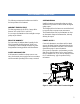
UNPACKING, SET-UP AND INSTALLATION ONLY SKILLED PERSONNEL SHOULD PERFORM INSTALLATION. READ AND COMPLY WITH ALL WARNINGS AND FOLLOW THE PROPER INSTALLATION PROCEDURES AND SAFETY GUIDELINES. • Take into account the weight of the laminator (570lb./258 kg shipping weight) when moving. Use equipment with which the weight can be safely lifted. The laminator is transported on a wooden pallet (skid). If your laminator is still on its skid, you can move it with a forklift to put it near its place of use.
UNPACKING YOUR LAMINATOR • • • • • • • • Remove the transport packing and the plastic shrink-wrap the laminator is wrapped in to avoid moisture penetration. Remove the accessory kit package from the top of the laminator, which includes the necessary tools for installation. Remove the footswitch from the top of the laminator and remove the foam wrapped around it. Place the footswitch in a position that is accessible while feeding images. Remove the protective foam wrapped around the front table.
IMPORTANT SAFEGUARDS SAFETY SYMBOLS USED ON THE LAMINATOR IMPORTANT! Read and make sure you understand these safety and operating guidelines. WARNING! Make sure the power disconnect located on the left side stand leg is turned to the OFF position before removing the side plate covers for any maintenance. IMPORTANT! Do not place heavy objects on the power supply cord. ROTATING PARTS: RISK OF INJURY PREVENTATIVE MEASURES: CAUTION! Failure to use caution near rotating rollers could result in physical injury.
SAFETY FEATURES The SEAL ® Image® 410 Laminator is designed with safety and protective devices with the user’s safety of utmost consideration. However, following safe operating guidelines is still the responsibility of the operator. COVERED FOOT SWITCH: POWER DISCONNECT SWITCH: WARNING! On Domestic version laminators the foot switch overrides the photoelectric eyes. When the photo eye is blocked, a Flashing Light and a BUZZER sounds, warning of close proximity to the nip.
LAMINATOR FEATURES 2 3 5 4 6 7 1 3 9 8 4 Figure 4. Laminator Features 1. • 2. • 3. • 4. • 5. • 10 Digital Touch Pad Control Panel with LED indicators It allows the operator to use 9 preset heat and motor speed settings to match film applications. The operator can also customize these settings. Nip Motor driven roller height adjustment Allows for accurate roller nip setting with no need for an air compressor. Adjusts for the thickness of the material to be processed.
CONTROL PANEL 1. Nip Adjustment Button: Press the UP arrow once to raise one setting. Press and hold to raise multiple settings. Press the DOWN arrow once to lower one setting. Press and hold to lower multiple settings. 2. Nip Indicator Lights (LEDs): Indicates which nip setting the rolls are currently set at. 3. Main Power On/Off (Stand-by) Button: Press this button to turn ON or OFF (put in Stand-by) the laminator. In Standby, the laminator power is still on, but all functions are disabled.
7. Reverse Mode Button: Reverses the direction of the roller rotation. NOTE: The Reverse Mode Button may only be used with the footswitch and when the motor is OFF. • To use the Reverse Mode: Press the Reverse Mode Button, the corresponding LED will be lit. Depress the footswitch to activate the reverse roller rotation. The Motor LED will be lit during operation. NOTE: The rollers will reverse at 1 fpm (.3mpm) and the speed cannot be adjusted.
PRESET PROGRAMS Settings provided are for optimal performance using the SEAL® Brands films listed. Purchasers should individually determine, prior to use, the suitability of each material for their specific purposes. PROGRAM 4: RIGID BACKLIT DISPLAYS Rigid Backlit Displays are created by face mounting an image to clear acrylic using an optically clear pressure sensitive adhesive. Use the laminator to coat the acrylic and mount the print.
CHECKING OPERATION After you are familiar with the control panel and its functions, check all operations. WARNING! If your laminator does not operate correctly, contact Technical Service immediately. CHECK THE MAIN POWER • Press the Main Power Stand-by button once and the temperature displays on the control panel should be lit. • If there is no power, refer to the Troubleshooting Page. CHECK THE EMERGENCY STOP BUTTONS • Press one of the Emergency Stop Buttons and the laminator will shut down.
S E T -UP AND OPERATION TEMPERATURE SETTINGS HOW TO SET THE ROLLER NIP • Select the film(s) that you will use on the top (and bottom) of the images. • First, determine the thickness of the board that you will use for mounting. • Check which temperature setting is recommended for your SEAL ® Brands material (see literature enclosed in your material box). • Adjust the nip setting by pressing the UP or DOWN arrow until the desired measurement corresponds with the thickness of board being used.
IMPORTANT! The position of all films, boards, rolls of media and cardboard cores for wind-ups must be set central in the laminator to ensure optimum quality and correct tracking. SETTING THE UNWIND BRAKE TENSION • • • IMPORTANT! The brake tension greatly affects the smooth flow of the laminating film. Turning the unwind brake in a counter-clockwise direction increases the braking tension applied on the laminate. Turning the unwind brake in a clockwise direction decreases the braking tension.
WEBBING FILMS WITHOUT A RELEASE LINER The following are the basic webbing procedures for webbing films without a release liner: • Select films slightly wider than the image to allow for a border without film waste. A border of 1/8” to 1/4” (3-6mm) is adequate. • Ensure the main roller’s temperatures are set according to the recommendations of the laminates being used (see literature enclosed in your material box).
WEBBING FILMS WITH A RELEASE LINER The following are the basic webbing procedures for webbing films with a release liner: • Select films slightly wider than the image to allow for a border without film waste. A border of 1/8” to 1/4” (3 - 6mm) is adequate. • Ensure the main roller’s temperatures are set according to the recommendations of the laminates being used. • Once the laminator reaches operating temperature, stop the laminator and raise the top roller.
DECALING (HEAT -ACTIVATED) This process involves applying a hot film to the top and a cold backing adhesive to the bottom of the graphic. This process can be used to create self-adhesive images for mounting down onto various substrates. After performing this process, follow the Mounting Instructions in the manual to apply the decal to a substrate. It is important to follow the webbing instructions for films specific for your location.
DECALING (PRESSURE- SENSITIVE) This process involves applying a cold pressure-sensitive over-laminate to the top and a cold pressure-sensitive mounting adhesive to the bottom of a graphic. If desired, set the top roller’s temperature to 120° F (49° C). Using heat-assist may improve the adhesive bonding of the laminate. This process can be used to create self-adhesive images for mounting down onto various substrates.
MOUNTING This process involves mounting previously prepared decals onto a substrate. No films or adhesives are required for this process. • TO MOUNT DECALS ONTO A SUBSTRATE • • Place the mounting board on a flat surface. • Lay your image face down on the mounting board and expose approximately 1” (25 mm) of the adhesive by peeling back the release liner along one of the edges. • Fold the release liner back making an even crease.
ONE STEP MOUNTING AND LAMINATING This process allows you to decal and mount in one step by using a mounting board with heat activated adhesive on one side MEDIA: INK JET, ELECTROSTATIC, AND PHOTOGRAPHIC FILMS: WEBBING PROCEDURE IMPORTANT! Ensure that the Nip setting corresponds to the board thickness. • Pull the film down from the top unwind shaft, and place it evenly over the face of the top roller. • Use a piece of leader board to hold the laminate under the top roller.
ENCAPSULATING This process involves completely sealing an image between two films. It is important to follow the webbing instructions for films specific for your location. MEDIA: INK JET, ELECTROSTATIC, AND PHOTOGRAPHIC NOTE! Web the top laminate following the basic procedures for webbing films w/o a release liner. FILMS: -- -- -- Top Unwind: Heat-activated Laminate 3 – 5 Mil ____ Bott.
P R E -COATING BOARDS This process is used to coat substrates with a selfadhesive coating onto which images can be mounted. Images can then be mounted on the substrate. This same process is used to create a sled. NOTE: When coating boards, ensure that the next board to be coated follows the previous board without any gaps.
APPLYING AN OVERLAMINATE This process involves applying an over laminate to an image with the use of a sled or pre-coated substrate. PREPARATION: • Set your nip in accordance with the thickness of the pre-coated board you will be using. • Load a roll of pressure sensitive laminating film on the top unwind shaft. • Do not remove the release liner from the sled. WEBBING PROCEDURE • Pull the film down from the top unwind. Separate the film from the release liner and lay the film over the top roller.
PROCESS CONTROL SHEET Process: _________________________________ Application Use: ___________________________ Top Unwind Shaft:__________________________ Bottom Unwind Shaft: _______________________ CONTROL PANEL SETTINGS Top Roller Temp: __________________________ Bottom Roller Temp: ________________________ Motor Speed Setting: ________________________ Program Preset ____________________________ NOTE: We recommend that you make a photocopy of this page.
CLEANING / MAINTAINING YOUR LAMINATOR CLEANING THE LAMINATOR • The laminator may be cleaned with a lint-free cloth, lightly dampened with a mild soap and water solution. Do not use spray-on cleaners. Do not immerse any part of the laminator in water or other liquids. • Do not use an abrasive cleaner, which can damage the painted surfaces. • Do not allow water or liquids to enter the electrical circuits, which may cause personal injury and/or damage the equipment when power is applied.
PERIODIC MAINTENANCE SHEET CHAIN T ENSION ADJUSTMENT / OIL CHAIN ** SAFETY CHECK AFTER SERVICING NOTE: Enter dates of service and initials of service personnel. We recommend that you make a photocopy of this page, tape it to the inside of the Side Plate Cover and use this to record dates that authorized safety or maintenance personnel perform these laminator maintenance procedures. Proper maintenance of your laminator ensures receiving many years of profit from your investment.
ERROR CODES THE FOLLOWING DESCRIBES THE DETAILS OF THE ERROR CODES: • The machine shuts down and the display starts blinking. • This means that the software has detected an error in the system. • The numbers on the displays tell you what error has occurred. • • The speed display will show the error level. The top temperature display will show the error data. • • These displays are used to find the problem. The bottom temperature display shows the current running program number.
TROUBLESHOOTING GUIDE Problem Solution The laminator will not turn on. • Check if the power cable is plugged into the mains wall outlet. • Check the Main Power Stand-by Button. The corresponding LED should be lit. • Make sure that the Emergency Stop buttons were not activated. Rotate to reset. • Unplug the laminator and check the circuit breakers under the left side plate. Check the fuse in the power supply. Only authorized safety or maintenance personnel should do this.
LOCATION OF BREAKERS • 1. Motor Breaker (0.8 Amp)– Located under the Right side plate. • 2. Control Power (2 Amp) – Located under the Left side plate. • 3. Top Heater (8 Amp) – Located under the Left side plate. • 4. Bottom Heater (8 Amp) – Located under the Left side plate. • 5. Common (16 Amp) for Domestic only – Located under the Left side plate. NOTE: All breakers are visible and can be reset, from the outside of the laminator.
GLOSSARY OF TERMS DECAL: OUT-FEED: An image that has been laminated on top (either heatactivated or pressure-sensitive) with an adhesive backing The side of the laminator from which completed images emerge FILM: A synonym for laminate. The material used in the laminating and encapsulating process PRE-COATING: The process of coating a substrate with an adhesive mounting film onto which an image can be mounted. PRESS: HEAT-ACTIVATED FILMS: Films with an adhesive that is activated when heat is applied.
SPARE PARTS LIST Please contact Technical Service for replacement parts.
TECHNICAL SPECIFICATIONS M ECHANICAL Dimensions (H x W x D) 62”w x 30”d x 47”h (157 cm x 76 cm x 119 cm) Net Weight 480 lbs. (218 kg) Shipping Weight 570 lbs. (258 kg) Roller Construction High release silicone-covered rollers PROCESS Max. Working Width 43” (110 cm) maximum Max. Roller Speed 10 fpm (3.1 mpm) Core Inner Diameter 3” (7.6 cm) Maximum Material Outside Diameter 8” (20.3 cm) Maximum Roller Opening 1.125” (2.86 cm) Maximum Board Thickness 1” (2.
LIMITED WARRANTY SEAL ® Graphics warrants to the original consumer purchaser that each new SEAL ® Image® Laminator, which proves defective in materials or workmanship within the applicable warranty period, will be repaired or, at our option, replaced without charge. Effective November 1st, 2002 the applicable warranty period for New Equipment shall be one year (parts), six months (labor and rollers) from date of purchase.
SEAL BRANDS TECHNICAL SERVICE SEAL BRANDS TECHNICAL SERVICE – EUROPE AND ASIA PACIFIC (For technical assistance & service) (For technical assistance & service) Tel: 1-800-486-6502 For UK: Tel: +44 1268 722 400 Fax: 1-800-966-4554 Fax: +44 1268 729 442 or +44 870 125 5798 For NL: Tel: +31 572 345 500 Fax: +31 572 345 501 SEAL BRANDS CUSTOMER SERVICE SEAL BRANDS CUSTOMER SERVICE – EUROPE AND ASIA PACIFIC (For information and placing orders) (For information and placing orders) Tel: 1-800-257-7