
Owner manual


10
Dometic Freshwater Tank MonitorInstallation
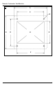
6.3 Probe Cap
(g.
3
B, page 2)
Caution!
Do not install probe cap in fuel tank.NeverinstallDometicprobecapwithoatswitches
into a tank that contains anything other than fresh water, gray water or waste water.
1. Loosen compression nuts on adjustable probes and install probe cap into tank. Following num-
bers printed on top of probe cap, slide the “1” probe (g.
3
B4,page3)downuntiltheoat
touches the bottom of the tank. Tighten “1” compression nut and mark the probe tube at the top
of the nut. Do not cut the probe tube at this mark. Loosen the compression nut, slide the probe
up, and carefully cut the “1” probe tube 42 mm (1.625 inches) below the mark without damaging
thewiresinsidethetube.Pullthewiresthroughtheblackwirecoverandpushtheprobedown
into the compression nut until the black wire cover touches the compression nut. The recessed
shoulderoftheoat,ortheletters“NO”,shouldbefacingdown(B5).
2. Remove probe cap from tank and adjust the “2” probe (g.
3
B 6, page 3) for one-half full level
forfreshwatertank.Tightenthecompressionnutandcuttheprobetubeoff10mm(0.375inch)
above the compression nut without damaging the wires. Slip the black wire cover onto the top of
thetube.Therecessedshoulderoftheoat,ortheletters“NO”,shouldbefacingdown(B7).
3. Route18-gaugestrandedcopperwiresfrommonitorpanelandDCgroundsourcetotheprobe
cap.Usequick-disconnectterminalsonoatswitchwirestopreventtwistingwireswhenremov-
ing the cap. With cap removed from tank, connect the wires according to the wiring diagram
(g.
4
,page3),turnonelectricalpowertosystem,andtesttheoatsbymovingthemupand
downandmonitoringtheDTMF04panel.Disconnectthewiresandinstalltheprobecapand
O-ring into the tank. Reconnect the wires.
6.4 Key to DTMF04 system wiring (g.
4
, page 3)
Ref. Description
A DTMF04indicatorpanel
B Freshwater tank
C 12VDC
D 24VDC
E VDCground
F 1-amp circuit breaker or fuse
G Red
H Blue
I Black
J Green
Ref. Description
K Yellow
L Orange
M Full level probe
N Mid level probe
O Low/Empty level probe
P 12or24VDC
Q Water pump circuit breaker or fuse
R +VDCtofreshwaterpump
Notes:
1.Dashedlineindicates14gaugeorlargerstranded
copperwireisrequired.
2. Other wire can be 18 gauge stranded copper wire
or larger.