
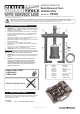
User Manual

3. OPERATION
Certain parts may need to be removed from the vehicle to allow
access to the rear trailing arm. Refer to the vehicle manufacturer’s
service instructions, or a proprietary manual to carry this out.
NOTE! This tool will insert the bush to the correct depth, but
before installing the new bush, refer to the vehicle manufacturer’s
service instructions, or a proprietary manual, to establish the
correct horizontal alignment / positioning of the bush.
IMPORTANT:
Ensure that the area around the bush is thoroughly cleaned. •
The threads on this tool should also be thoroughly lubricated in use. •
An Impact Socket must NOT be used with this tool. •
Stripped threads and bent thrust cups are not accepted •
warranty claims on this tool.
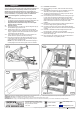
3.1. Removal of bush.
3.1.1. Undo the allen bolt (5) and remove it, plus the alignment pin (8)
and installation ring (9) from the tool.
3.1.2. Position the tool as in Fig.1. Loosen off the 14mm bolts and
adjust the hooks so that they securely grip onto the trailing arm
(Fig.2), re-tighten the bolts. Ensure that the face of the pusher
is centrally lined up with the bush.
3.1.3. Using a 24mm spanner, turn the force screw clockwise. The
pusher will start to push the bush from its housing.
3.1.4. Keep turning until the bush has been pushed all the way out
of the housing. Take care as the bush and assembly may fall
away when the bush is fully removed.
NOTE! If any undue resistance is felt, check that everything is
correctly aligned. The bush will only push out in one direction.
3.2. Installation of new bush.
3.2.1. Before installing a new bush, clean the inside of the housing
thoroughly.
3.2.2. Re-assemble the alignment pin (8), the installation ring (9) and
allen bolt (5) to the pusher and tighten the allen bolt.
3.2.3. The bush should be aligned in the housing as per the vehicle
manufacturer’s service instructions.
3.2.4. Fit the assembly over the bush and onto the housing as in Fig.3.
Loosen off the 14mm bolts and adjust the hooks so that they
securely grip onto the trailing arm, re-tighten the bolts. The
sighting windows in the sides of the unit allow for checks on the
bush to ensure that it is still in the correct position whilst
installing.
3.2.5. Double check to make sure that everything is aligned and that
the bush is sitting squarely against the housing.
3.2.6. Commence turning the force screw to start installing the bush
into the housing, check to make sure that the bush is still aligned
correctly.
3.2.7. Continue to install the bush until the alignment pin touches
thehousing(g.4),thebushisnowfullyinstalled.
3.2.8. Disassemble the tool, clean and lubricate it before returning the
parts to the storage case.
3.2.9.Re-tallpartstothe vehicle as per the vehicle manufacturer’s
service instructions or a proprietary manual.
NOTE: It is our policy to continually improve products and as such we reserve the right to alter data, specifications and component parts without prior notice.
IMPORTANT: No liability is accepted for incorrect use of this product.
WARRANTY: Guarantee is 12 months from purchase date, proof of which will be required for any claim.
INFORMATION: For a copy of our latest catalogue and promotions call us on 01284 757525 and leave your full name and address, including postcode.
Sole UK Distributor, Sealey Group,
Kempson Way, Suffolk Business Park,
Bury St. Edmunds, Suffolk,
IP32 7AR
Original Language Version
VS726 Issue: 1 - 28/10/10
01284 757500
01284 703534
sales@sealey.co.uk
www.sealey.co.uk
Web
email
Fig.1
Fig.2
Fig.4
Fig.3