
User Manual

Original Language Version
VS710 Issue No.1 30/10/09
2. INSTRUCTIONS
2.1 Raise the vehicle and ensure that it is adequately supported before beginning work.
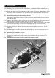
2.1.1 Referring to the manufacturer's servicing manual, dismantle the suspension/wheel hub as
directed until the outer end of the drive shaft (H) is free and accessible as shown below.
2.1.2 Detach the rubber boot (G) from the back of the constant velocity joint (K) and slide it up the
drive shaft. Clean the grease from the joint and the drive shaft especially in the grooved/
shouldered area (J).
2.2 Assemble the tool to the drive shaft as follows:
2.2.1 Take the main tool (B) and slide the ring over the end of the drive shaft so that the arms lie
either side of the constant velocity joint and at least 5mm of the threaded end of the shaft
lies within the ring.
2.2.2 Take the lower clamp (C) and insert the two pins (D) through the holes in the clamp arms so
that the clamp touches the drive shaft within the grooved/ shouldered area (J).
2.2.3 Lower the upper clamp (E) over the lower clamp pins (D). Insert the two bolts (F) and thread
them into the lower clamp as shown below and tighten equally until the tool is firmly
attached to the drive shaft.
2.2.4 Screw the hub nut (A) onto the end of the drive shaft until it faces onto the ring. Do not
tighten yet.
2.3 Releasing joint retained by sprung ring (no circlip).
2.3.1 Gradually tighten the hub nut to compress the sprung ring. Continue winding the hub nut
until the joint is released.
2.4 Releasing joint retained by a circlip.
2.4.1 Where the joint is retained by a circlip it will be necessary to compress the clip using a
suitable tool. Keep the circlip under tension whilst winding the hub nut until the joint is
released.
2.5 Disassemble the tool from the drive shaft and remove the joint.