
User Manual

VSE127H05 Issue No. 1 - 10/11/09
NOTE: It is our policy to continually improve products and as such we reserve the right to alter data, specifications and component parts without prior notice.
IMPORTANT: No liability is accepted for incorrect use of this product.
WARRANTY: Guarantee is 12 months from purchase date, proof of which will be required for any claim.
INFORMATION: For a copy of our latest catalogue and promotions call us on 01284 757525 and leave your full name and address, including postcode.
Sole UK Distributor, Sealey Group,
Kempson Way, Suffolk Business Park,
Bury St. Edmunds, Suffolk,
IP32 7AR
01284 757500
01284 703534
sales@sealey.co.uk
www.sealey.co.uk
Web
email
Original Language Version
Fig.3
Fig.4
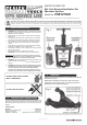
3.1 Ball Joint Removal. To remove the ball joint you will need to
use adaptors A & B in conjunction with Sealey Hydraulic Ball
Joint Remover/Installer Kit (Model No. VSE127H).
3.1.1 Referring to the vehicle manufacturers servicing information
disassemble the necessary suspension and steering
components to gain access to the ball joint for removal.
3.1.2 Rotate the hydraulic unit anticlockwise within the press frame
until the bottom of the unit is level with the underside of the top
bar. Ensure that the black ring is properly seated in the base of
the press (see fig.1-Z) and place adaptor (B) into the ring with
the narrower section upwards.
3.1.3 Holding the hydraulic unit, take the press to the exposed ball
joint and introduce it into adaptor (B). Lift the press so that
adaptor (B) bears directly onto the casting that holds the ball
joint. See ‘X’ inset in fig.3.
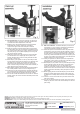
3.1.4 Slide adaptor (A) into position on the top of the ball joint itself
ensuring that the surface with the indent in it is uppermost. Turn
the handle on the hydraulic unit clockwise so that the ram
descends and the steel ball at the end of the ram enters the
indent. Continue turning the handle until the whole assembly is
firmly clamped onto the ball joint housing.
3.1.5 Before applying pressure to the ball joint ensure that the adaptors
are correctly seated as shown in the inset diagram in fig.3.
3.1.6 Continue to turn the ram handle slowly clockwise until the ball
joint is fully ejected. Be prepared for the sudden release of the
ball joint at which point the assembly will become unstable.
3.1.7 Turn the ram handle anticlockwise to back off the ram. Remove
adaptor (A) first, then remove the whole assembly from the ball
joint housing.
3.2 Ball Joint Installation. To install the ball joint you will need to
use adaptors C & D in conjunction with Sealey Hydraulic Ball
Joint Remover/Installer Kit (Model No. VSE127H).
3.2.1 Rotate the hydraulic unit anticlockwise within the press frame
until the bottom of the unit is level with the underside of the top
bar. Ensure that the black ring is properly seated in the base of
the press (see fig.1-Z) and place the closed end of adaptor (D)
into the ring. Place the threaded stub of the new ball joint (J) into
the open end of adaptor (D) so that the body of the ball joint sits
inside the flange in the top of the adaptor.
3.2.2 Holding the hydraulic unit, take the press to the exposed ball
joint housing. Lift the press so that the body of the ball joint (J) is
positioned ready to enter the ball joint housing.
3.2.3 Slide adaptor (C) into position on the top of the ball joint housing
ensuring that the surface with the indent in it is uppermost as
seen in the inset diagram in fig.4. Turn the handle on the
hydraulic unit clockwise so that the ram descends and the steel
ball at the end of the ram enters the indent. Continue turning the
handle until the whole assembly is firmly clamped onto the ball
joint housing.
3.2.4 Before applying pressure to insert the ball joint (J) ensure that the
ball joint is correctly aligned with the opening in the housing and
the adaptors are correctly seated as shown in the inset diagram
in fig.4.
3.2.5 Continue to turn the ram handle slowly clockwise until the ball
joint is fully inserted.
3.2.6 Turn the ram handle anticlockwise to back off the ram. Remove
adaptor (C) first, then remove the whole assembly from the ball
joint housing.