
Instruction Manual

8 DO NOT use the soldering iron for any purpose other than that for which they have been designed.
8 DO NOT touch the work piece immediately after working on it, as it will be very hot. Allow it to cool.
8 DO NOT allow untrained persons or children to operate the soldering iron.
8 DO NOT operate the soldering iron if damaged.
8 DO NOT hold the work piece by hand.
9 When finished working, store the soldering iron in a safe, dry, childproof location.
2. i INTRODUCTION
Comprehensive soldering kit comprising a 100W instant heat soldering gun, a 30W soldering iron with stand, a third hand support, solder sucker,
scraper/probe, spare soldering tips and a roll of ux cored solder wire. Soldering irons tted with BS approved 3 pin 230V/13Amp plugs.
3. CONTENTS
• Instant heat soldering gun (100W)
• Soldering iron with stand (30W)
• Soldering stand
• Solder sucker
• Scraper/probe
• Spare soldering tip
• Roll of ux cored solder wire
4. OPERATION
4.1. USING THE 30WATT SOLDERING IRON.
4.1.1. The 30Watt soldering iron is primarily intended for the
soldering of electrical joints such as the attachment of
components to printed circuit boards and the connection of
leads to plugs and sockets used in electronics.
(Where delicate electronic components are concerned that
may be damaged by excessive heat, the wire being soldered
should be held with a pair of thin nosed pliers on the
opposite side of the board so that some of the heat
generated by the soldering process is transferred to the pliers.)
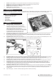
4.1.2. Preparing the iron stand. Before using the soldering iron, set up the metal stand provided by bending the centre section upwards so
that it is nearly vertical to the rest of the stand as shown in fig.2. Rest the soldering iron on the stand. Plug the iron into the mains and
switch on leaving the iron on the stand to heat up.
4.1.3. Preparation of iron. When the iron is up to temperature, “tin” the tip by melting a thin layer of solder all over the flattened part of it. If any
difficulty is experienced in getting the solder to take to the tip use a proprietary tip cleaner/tinning product.
4.1.4. Preparation of parts. The items to be soldered must be perfectly clean and free from grease. Ideally, the two items to be joined (such as
the end of a wire and a switch terminal) should be individually tinned before being brought together to ensure a good joint.
4.1.5. Holding the work. Ensure that the items to be soldered are readily accessible and firmly held. The stand provided can be used to hold
two items together for soldering leaving both hands free to manipulate the iron and the solder. (See fig.1)
4.1.6. Soldering. Bring the soldering iron and the solder to the joint simultaneously. (See fig.1) Leave the iron on the joint just long enough to
melt the solder so that it flows onto the two parts to be joined. Remove the iron and place it on the stand. Leave the joint to cool.
4.1.7. Changing tips. After a prolonged period of service the tip may become pitted and need replacing. Wait till the iron is completely cool.
Loosen the tip retaining nut and pull out the old tip with a pair of pliers. Insert the new tip and twist it into the orientation you require.
Lock the tip in place by tightening the the retaining screw. See fig.3.
4.1.8. Maintenance. DO NOT allow solder to accumulate where the tip enters the iron as this may make the tip difficult to remove. DO NOT get
solder deposits on the tip retaining screw as it may prevent a screwdriver fitting into the cross head. Periodically loosen the tip retaining
screw and rotate the tip in the iron to prevent it seizing into the body. Use a proprietary tip cleaner/tinner to keep the tip clean and
correctly tinned.
4.1.9. Spare soldering tips : - Model No. SD30/ST (straight tip), Model No. SD30/CT (curved tip)
fig.1
fig.2
fig.3
Original Language Version
© Jack Sealey Limited
SDK300K Issue 4(F) 23/02/22