
Instruction Manual

5. OPERATION
5.1. CONNECTING LEADS
5.1.1. On MΩ Range:ConnecttheredtestleadintotheVΩterminalandtheblackterminalintotheCOMterminal.
5.1.2. On 200Ω and ACV Range:Connecttheredtestleadintothe“VΩ”terminalandtheblackleadintoterminal“COM”.
5.2. TEST LEADS CHECK
5.2.1. Settherangeselectswitchtothe200Ωrange.Withthetipandalligatorclipofthetestleadsconnected,theindicatorshouldread
00.0Ω.Whentheleadsarenotconnectedthedisplaywillreadinnityindicatedby“1”.Thiswillensurethattestleadareunder
working condition.
5.3. BATTERY CHECK AND REPLACEMENT
5.3.1. IfbatterypowerisinsufcienttheLCDwilldisplay.6x1.5VAAbatteriesarerequired.
5.3.2. Removethefourscrewswhichholdthebatterycovertotbatteries.
5.4. INSULATION RESISTANCE MEASUREMENT
5.4.1. Measurements at 200mΩ/250V
5.4.2. Thisisthevoltageusedforthemajorityofinsulationresistancetestsonnormalinstallations.
5.4.2.1. To measure insulation resistance, press the test button to power on the tester. The LCD will display the insulation resistance.
Section VII indicated that subdivision of large installations might be necessary because of the large number of parallel insulation
resistance. In such a case, an installation may be divided into sections, each being separately tested. Each section must have not
less than fifty outlets, an outlet being a switch, socket, lighting point etc. A switched socket counts as one outlet. The minimum
acceptableinsulationresistanceis1MΩ.Foralargeinstallation,thecapacitanceoftheinsulationwillbehigh,anditwilltake
longer for it to become charged by the direct testing voltage. Care must be taken not to take a reading until there is a steady
reading, indicating that the charging process is complete.
NOTE: The charge stored in the insulation will be discharged automatically when the test button is released. Be careful not to turn
the range switch knob whilst the test button is pressed, or the instrument will be damaged.
5.4.3. Measurements at 2000mΩ/1000V
5.4.3.1. Somespecicationsrequiretestingat1000V.Thisvoltagemustalsobeselectedwherethesupplyvoltageoftheinstallationis
between 500V and 1000V. First, set the range switch to 1000V and then proceed as indicated above for 500V testing. The above
note also applies to testing at 1000V. In addition the following applies.
NOTE: Make sure that the circuit under does not include components which will be damaged by the 1000V applied. Many normal
components of an installation are likely to be damaged if tested at 1000V. Examples are power factor correction capacitors, low
voltagemineralinsulatedcables,electroniclightdimmers,electronicballastsandstartersforuorescentlampsetc.
5.5. LOCK POWER ON FEATURE
5.5.3.1. For hands free operation a lock power on feature is incorporated on the press to test button. Set LOCK button to lock test voltage,
pressing it again will turn the tester off.
5.6. LOW RESISTANCE (CONTINUITY MEASUREMENTS)
5.6.1. Settherangeswitchto200Ωposition.
5.6.2. ConnecttheredtestleadtotheVΩterminalandblacktotheCOMterminal.
5.6.3. Connectthetipsofthetestleadstobothendsofthecircuitundertest.ReadresistanceinΩontheLCD.
5.6.4. Whentheimpedanceoncircuitisbelowapproximately40Ω.Itwillindicatebyacontinuousbeeper.
5.7. AC/DC VOLTAGE MEASUREMENTS
5.7.1. Set the range switch to ACV or DCV position.
5.7.2. Connectredtestleadto“VΩ”terminalandblacktestleadtoterminal“COM”.
5.7.3. Connect test prods of test leads IN PARALLEL to the circuit being measured.
5.7.4. Read the voltage value on LCD.
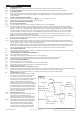
5.8. POWER TOOLS AND SMALL APPLIANCES See (g.1)
5.8.1. This test would also apply to other similar equipment that has a power cable. For double insulated power tools, the insulation tester
lead shown connected to the housing would be connected to some metal part of the tool (e.g chuck or blade).
NOTE: Theswitchofthedevicemustbeinthe“ON”positionandthemainspowershouldbedisconnected.
5.9. AC MOTORS Refer to (g.1)
Disconnect the motor from the line by disconnecting
the wires at the motor terminals or by opening the
main switch. If the main switch is used and the
motor also has a starter then the starter must be held,
bysomemeans,inthe“ON”position.Inthelatter
case, the measured resistance will include the
resistance of the motor, wire and all other components
between the motor and the main switch. If a weakness
is indicated, the motor and other components should
be checked individually. If the motor is disconnected
at the motor terminals, connect one insulation tester
lead to the grounded motor housing and the other
lead to one of the motor leads.
5.10. DC MOTORS Refer to (g.1)
5.10.1. Disconnect the motor from the line. To test the brush
rigging,eldcoilsandarmatureconnectone
insulation tester lead to the grounded motor housing
and the other lead to the brush on the commutator.
5.10.2. If the resistance measurement indicates a weakness,
raise the brushes off the commutator and separately
testthearmature,eldcoilsandbrushriggingby
connecting one lead to each of them individually,
leaving the other connected to the grounded motor
housing. The above also applies to DC generators.
Original Language Version
© Jack Sealey Limited
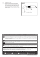
g.1
TA319.V2Issue2(5,4)12/08/22
Insulation Tester
Connect to Motor
side of switch
Line
Main
Switch
Starter
(Must be in
“On Postion”)
Motor
Ground
Connect to
Motor Housing
(Ground)