EX800-Series EX810 EX820 EX830 ISO 9 0 0 1 : 2 0 0 8 CERTIFIED COMPANY E X 8 0 0- S E R I E S E L E C T R O M A G N E T I C F L O W S E N S O R I N S T R U C T I O N S ELECTROMAGNETIC FLOW SENSOR INSTRUCTIONS
TABLE OF CONTENTS General Information Features, Specifications........................................................................................................................................Page 1 Installation Distorted Flows, Fitting Installation, Chemical Injection or Fertigation, Meter Installation, Positioning the Meter.............................................................................................................................................
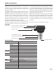
GENERAL INFORMATION EX800-Series insertion electromagnetic flowmeters are designed for use with conductive liquids in 1 to 12” pipe. A choice of materials (stainless steel, brass, and PVC) allows the meter to adapt to a range of temperature, pressure, and corrosive environments. The EX800 is highly suitable for difficult applications with changing viscosities and pulsating flows, such as air-driven diaphragm pumps.
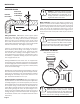
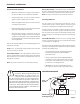
INSTALLATION DISTORTED FLOWS Distorted Flow Profile Caution: In chemical injection or fertigation applications, install chemical injection point downstream of magmeter, or far enough upstream to allow complete mixing of fluids before the meter. Faster Flow Causes Meter To Read High 10X 5X Fitting Installation. EX800-Series meters require special fittings that ensure that the flow sensor is installed to the correct depth. The fitting must be installed in the pipeline before the meter can be installed.
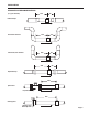
INSTALLATION STRAIGHT PIPE RECOMMENDATIONS (X = pipe diameter) 10X 5X Reduced Pipe 10X Two Elbows In Plane Two Elbows, Out Of Plane 5X 20X 5X 20X 5X Expanded Pipe 30X Spiral Flow Propeller Meter 50X Swirling Flow Partially Open Butterfly Valve Page 3
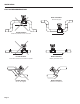
INSTALLATION FULL PIPE RECOMMENDATIONS Better Installation: Ensures full pipe Possible Problem: Allows air pockets to form at sensor Page 4 Possible Problem: Post-valve cavitation can create air pocket Better Installation: Keeps pipe full at sensor Possible Problem: Air can be trapped Better Installation: Allows air to bleed off
ELECTRICAL CONNECTIONS • Whenever possible avoid running control cables in the same conduit with or bundled with AC power. Reverse Flow Output: Reverse flow output is available as an option. This open-collector isolated output does not supply power. It functions like a polarity-sensitive switch closure. Note: This output is limited to 6 mA at 30 Vdc maximum. • Using shielded cable, be sure to connect shield to ground at power supply end of the cable.
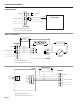
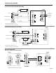
CONNECTIONS DIAGRAMS COUNTER OR PLC + _ 12 - 24 Vdc Power Forward Output + _ Reverse Output (Option-15 only) + _ COUNTER OR PLC DIGITAL INPUT Green Max. 6 mA, 30 Vdc White Max. 6 mA 30 Vdc EX SERIES *See Dual FT420 Diagram for an example of bidirectional connections.
CONNECTIONS DIAGRAMS FT420 DISPLAY AND PROPORTIONAL FEED _ Power + _ + Red White Black + _ + _ Pulse Pass-Thru Power 4-20mA *See Dual FT420 Diagram for an example of bidirectional connections.
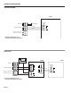
CONNECTIONS DIAGRAMS DL76 DATA LOGGER DL76 Power Sensor Input 12 - 24 Vdc Green Forward Output White Reverse Output (Option-15 only) EX SERIES *See Dual FT420 Diagram for an example of bidirectional connections. FT420/DL76 Power + 24 Vdc Power Black EX SERIES *See Dual FT420 Diagram for an example of bidirectional connections.
OPERATION & MAINTENANCE Zero Adjustment. When the EX800-Series is powered up and there is no flow, there should be no output pulses (or, if connected to the FT420, flow rate should read “0”). If there are pulses it may be necessary to adjust the flow meter under no-flow conditions after it has been installed. This should only be done if the indicated flow is low, near the lower cutoff. Reverse Output Option 1 Zero Adjust Pins 2 3 4 5 6 - + - + Forward Power Output M ax 30 .
CAUTION & TROUBLESHOOTING Caution: The electronics of the EX-Series meters are not field-repairable. Warranty is void if unauthorized repair is attempted TROUBLESHOOTING Problem Probable Cause Try... No pulse output Pipe not full Check plumbing Below minimum flow cutoff Check the presence of Flow LED (see pg.